Hi,
I just sold my receiver, and I am trying some cheap a$$ to survive until I save enough money for a processor or a high end receiver.
My configuration consist of:
-. Gefen HDMI to HDMI Plus Audio Converter, which is a good quality HDMI 7.1 DAC with some Cirrus Logic DAC and 2vRMS output (I have uploaded some pictures before)
Because the Gefen has HDMI 1.4 and only 1 input, I added an OREI HDMI Matrix 2x4 that supports 18Gbps HDMI signal.
-. After the DAC, signal goes to an ADAU 1452 4x8 DSP. I am planning on adding a second DSP to get 8x16 and use a dual gang potentiometer for volume control.
-. Final step, Class D Anaview/Abletec amplifiers.
So it's kind of a cheap miniDSP NANO AVR-HDA. So far it sounds good to my ears, and the possibilities SIGMASTUDIO offers are endless. Of course its a lot more work that running AudysseyXT and sure, you lose ATMOS, but you can certainly tailor the sound to your needs, and even active XO is quite simple with this setup.
The thing is I might replace my passive DIY speakers for some JBL 305/306/308 which are active speakers with active XO and DSP integrated.
So, my question is... would this DAC-ADC-DAC-ADC-DAC "damage" the signal? I am using this setup for movies and some music, but not critical listening, in fact I am using the DSP with a 48000hz sample rate to match my files sample rate.
Any help and/or comments would be greatly appreciated.
Attachments
"...would this DAC-ADC-DAC-ADC-DAC "damage" the signal?"
Absolutely, yes.
Audio will sound best going though a DAC only one time.
Absolutely, yes.
Audio will sound best going though a DAC only one time.
well, the possibility of only one dac is not viable, as I need to extract the audio signal from the hdmi (1 dac) and then feed the dsp, and after processing I need there another dac before the amps.
I know it might not be the best performing setup, just good enough, so getting active speakers might not be the step in the right direction.
I know it might not be the best performing setup, just good enough, so getting active speakers might not be the step in the right direction.
Hi,
I just sold my receiver, and I am trying some cheap a$$ to survive until I save enough money for a processor or a high end receiver.
My configuration consist of:
-. Gefen HDMI to HDMI Plus Audio Converter, which is a good quality HDMI 7.1 DAC with some Cirrus Logic DAC and 2vRMS output (I have uploaded some pictures before)
Because the Gefen has HDMI 1.4 and only 1 input, I added an OREI HDMI Matrix 2x4 that supports 18Gbps HDMI signal.
-. After the DAC, signal goes to an ADAU 1452 4x8 DSP. I am planning on adding a second DSP to get 8x16 and use a dual gang potentiometer for volume control.
-. Final step, Class D Anaview/Abletec amplifiers.
So it's kind of a cheap miniDSP NANO AVR-HDA. So far it sounds good to my ears, and the possibilities SIGMASTUDIO offers are endless. Of course its a lot more work that running AudysseyXT and sure, you lose ATMOS, but you can certainly tailor the sound to your needs, and even active XO is quite simple with this setup.
The thing is I might replace my passive DIY speakers for some JBL 305/306/308 which are active speakers with active XO and DSP integrated.
So, my question is... would this DAC-ADC-DAC-ADC-DAC "damage" the signal? I am using this setup for movies and some music, but not critical listening, in fact I am using the DSP with a 48000hz sample rate to match my files sample rate.
Any help and/or comments would be greatly appreciated.
Check out
5.1 channel preamp
It does not have DSP or channel routing though I have found only 1 instance where channels were not where
they belong. I"m looking at doing a new board with ADAU1701 DSP chips and a 12x8 switch for channel routing.
Hope this helps.
G²
Check out
5.1 channel preamp
It does not have DSP or channel routing though I have found only 1 instance where channels were not where
they belong. I"m looking at doing a new board with ADAU1701 DSP chips and a 12x8 switch for channel routing.
Hope this helps.
G²
I will check it. If you can offer a 5.1/7.1 preamp with HDMI (LPCM only) input and DSP processing for every channel, count me in with one board!
Maybe you can extract I2S signals after the HDMI decoder and before its internal dac?
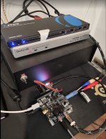
That sounds a little daunting as I don't have the schematics of the GEFEN audio extractor and my knowledge of electronics is not "PRO" level. Still, is there a way to identify I2S signals? Here are some internal pictures of my DAC: How bad is this DAC?
Looks like there are multiple dac chips. Your pic is too blurry for me to read the part numbers. So, you need to get the part number from the dac chips and look up the datasheets using Google search. Also, if you give us the dac part number, we can look it up too. There will be a pinout diagram showing which pins are the I2S input pins. You would need an oscilloscope to look at the signals.
Yes, there are 4 DAC chips (CIRRUS LOGIC 4353), as this is a 8 channel DAC (7.1 audio extractor).
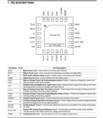
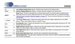
I uploaded a picture of the pinout...
About the osciloscope... Is there any cheap alternative? Like the ones sold in Aliexpress or Banggood?
Looking forward to your help
I uploaded a picture of the pinout...
About the osciloscope... Is there any cheap alternative? Like the ones sold in Aliexpress or Banggood?
Looking forward to your help
Attachments
Last edited:
The four signals of interest would be MCLK, SCLK, SDIN, and LRCK (and ground, typically one ground wire for each digital audio signal). Technically, MCLK is not one of the I2S/PCM bus signals, but you would need it too if you want to stay in one clock domain (although there are ways to get around that).
Regarding a scope, MCLK might be as much as 50MHz. A 50MHz square wave would look closer to a sine wave on a 100MHz scope. If you wanted to see the actual square shape you would need a much faster instrument. I guess you might take a look at the popular 50MHz to 100MHz scopes on Amazon to get an idea. That's probably about the minimum you would want if you would like to include digital audio as realistic part of your electronics hobby. Although new digital scopes have some nice features, an old analog scope from ebay or somewhere might be a lower cost option.
All the above having been said, some people have succeeded at routing and using digital audio signals without a scope. However, troubleshooting can be difficult, time-consuming, and frustrating for everyone: yourself, and whoever may be trying to assist you.
Last edited:
Thanks for your help!
I have a 3E audio DSP, which is a 2x4 and I think it has I2S input.
Should I try to wire the pins from the DAC to the DSP and see if I've got any sound?
An osciloscope like this should work?
Amazon.com: Quimat Q15001 - Osciloscopio digital TFT de 2,4" con fuente de alimentacion y sonda de cable BNC (acabado montado): Industrial & Scientific
Looks like the scope you linked to is 200kHz bandwidth, which is way too slow. You probably would want to have 2 input channels and a minimum of 50MHz bandwidth. For a new one you might be looking at: Amazon.com: Osciloscopio de almacenamiento digital Siglent: Industrial & Scientific
...or maybe 100MHz: Hantek DSO5102P Digital Storage Oscilloscope USB 100MHz 1GSa/s 40K, 2 Channel, 2CH: Amazon.com: Industrial & Scientific
A cheap used 60Mhz scope on ebay: Tektronix 2213 Analog Oscilloscope | eBay
Okay, lets talk about I2S a little. Three signals are shared (all the same) between the four dacs in your HDMI box. Those are: MCLK, SCLK, and LRCK. Each dac also receives a unique SDIN signal, which means there are 4 of them.
To extract those signals from the HDMI box it would be necessary to solder a small wire onto each signal. Its possible they have buried the signals where it would be difficult to get to them, or it could be they are fairly easy to get to. One would have to examine where those signals go into each dac and see if there are traces on the PCB leading away on the surface. If there are surface traces, then even better if they go to an SMD component as that might be an easy place to solder a wire on.
Another thing to understand is that I2S/PCM bus signals are not designed to be run long distances. Not more than s few CM wire length would be ideal, although people have run longer wires and gotten away with it in some cases.
It could also be that your DSP board would have no use for the HDMI box MCLK signal. If it uses a process called ASRC to convert the audio data to a new sample rate, then its I2S inputs may be limited to the remaining three signals (and ground).
It might be a good idea to examine the HDMI box PCB with a magnifying glass or maybe a 10x power microscope to see what there is in the way of exposed locations where the necessary signals could be picked up.
Last edited:
Thank you very much for your help!
I must be honest with you, I don't want to spend USD$100+ on a oscilloscope. I don't live in the US so I must add shipping and taxes, and the cost will match, almost, the price of nice receiver here.
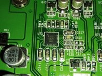
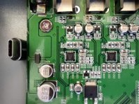
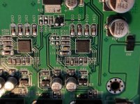
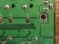
The signals don't seem to be buried in general. I uploaded some new pictures with more details and show some SMD components (caps and res). I placed a small USB-C adapter in one of the pictures for size comparison.
Obviously, the 4 pins I need do seem to be buried, so my only alternative would be to solder it directly to the QFN package...
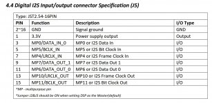
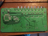
About the HDMI MCLK signal, it seems the DSP does not have use for it. I uploaded the pinout of my DSP's I2S port.
I must be honest with you, I don't want to spend USD$100+ on a oscilloscope. I don't live in the US so I must add shipping and taxes, and the cost will match, almost, the price of nice receiver here.
The signals don't seem to be buried in general. I uploaded some new pictures with more details and show some SMD components (caps and res). I placed a small USB-C adapter in one of the pictures for size comparison.
Obviously, the 4 pins I need do seem to be buried, so my only alternative would be to solder it directly to the QFN package...
About the HDMI MCLK signal, it seems the DSP does not have use for it. I uploaded the pinout of my DSP's I2S port.
Attachments
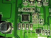
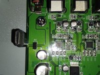
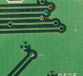
Looks like there are VIAs on traces going to the pins in question. Maybe easiest to scrape off the solder mask over the via with a tiny tool, then tin, then solder on some tiny wires. Attached below is a pic with the VIAs circled in red, and a rectangular area where it might be possible to scrape off some solder mask and attach signal grounds. Also a pic of the chip pinout. SCLK and LRCK would only be needed from one dac since they should be the same for all dacs. Sounds like you can skip MCLK altogether for this project.
Attachments
Last edited:
Regarding a scope, up to you what you want to do. Same for the other things we are talking about. Personally though, I count a 100MHz, 2-channel scope at essential for electronics. One like that is hardly exotic or high end, just a very basic tool.
Looks like there are VIAs on traces going to the pins in question. Maybe easiest to scrape off the solder mask over the via with a tiny tool, then tin, then solder on some tiny wires. Attached below is a pic with the VIAs circled in red, and a rectangular area where it might be possible to scrape off some solder mask and attach signal grounds. Also a pic of the chip pinout. SCLK and LRCK would only be needed from one dac since they should be the same for all dacs. Sounds like you can skip MCLK altogether for this project.
Thanks for your reply!
I will try to solder thru the VIA, but first i will check if they are blind or through, as maybe is easier to get them from the bottom of the PCB.
After that I will wire it to my DSP and report.
If I success this would be great for those searching for a cheap HDMI MULTICHANNEL DAC, as it will allow 8 channels of I2S signal to feed DSP's and high quality DAC's on the CHEAP.
Regarding the oscilloscope, I totally agree with you but right now is not in my priorities (at that price anyway). I have found a 100mhz oscilloscope like this:
Daniu ads5012h digital 2.4-inch tft screen anti-burn oscilloscope 500ms/s sampling rate 100mhz analog bandwidth support waveform storage and built-in large 3000mah capacity lithium battery Sale - Banggood.com
The 100MHz scope you linked to just now is probably far better than nothing. 2-channels would make it more useful in certain situations (that, or maybe at least having an external trigger input). Did you by chance read the first review for it:
"2019-11-24 09:45:52
It's a cheap scope with some limitations : It's not a real 100Mhz scope, the firmware is has some flaws and missing features, especially when saving samples (it's olny a screen choot). It can be useful on low frequency electronic works like Arduino,... My probe doesn't seems to work very well, hopefully I have another one. Some people are working to make a better firmware Reverse engineering FNIRSI-5012H - Page 1 Some videos about this miniscope https://www.youtu be.com/watch?v=SIH48bIUU00 Pocket 100MHZ oscilloscope?? part1 - intro and teardown - YouTube "
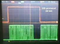
FWIW, the majority (>50%) of my own scope use is only one channel. However, I could imagine you wanting to see two channels at once at some point, say, in order to compare two waveforms or their relative timing. Consider having two in order to help figure out the I2S/PCM format as shown in the pic below.
"2019-11-24 09:45:52
It's a cheap scope with some limitations : It's not a real 100Mhz scope, the firmware is has some flaws and missing features, especially when saving samples (it's olny a screen choot). It can be useful on low frequency electronic works like Arduino,... My probe doesn't seems to work very well, hopefully I have another one. Some people are working to make a better firmware Reverse engineering FNIRSI-5012H - Page 1 Some videos about this miniscope https://www.youtu be.com/watch?v=SIH48bIUU00 Pocket 100MHZ oscilloscope?? part1 - intro and teardown - YouTube "
FWIW, the majority (>50%) of my own scope use is only one channel. However, I could imagine you wanting to see two channels at once at some point, say, in order to compare two waveforms or their relative timing. Consider having two in order to help figure out the I2S/PCM format as shown in the pic below.
Attachments
Last edited:
Sorry, did get notice on this reply.
Thanks for the information. I already bought that scope, but it's coming from China so I will have to wait a few months.
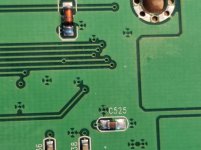
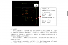
Last night I removed the HDMI Audio Extractor's PCB from the case to check if the VIAs are through, and they are! So it's a little bit easier to solder some cables from the back.
I have attached some pictures, and it would be great if someone could help me validate my pinout scheme.
Also, from previous posts, I need only one set of MCLK, SCLK, LRCK and Ground (digital), and one SDIN for every 2 channel (one for every DAC). Correct?
Finally, how long can I2S cables be? Is it OK 10 centimeters?
Thanks for the information. I already bought that scope, but it's coming from China so I will have to wait a few months.
Last night I removed the HDMI Audio Extractor's PCB from the case to check if the VIAs are through, and they are! So it's a little bit easier to solder some cables from the back.
I have attached some pictures, and it would be great if someone could help me validate my pinout scheme.
Also, from previous posts, I need only one set of MCLK, SCLK, LRCK and Ground (digital), and one SDIN for every 2 channel (one for every DAC). Correct?
Finally, how long can I2S cables be? Is it OK 10 centimeters?
Attachments

You can always scrape off a tiny bit of solder mask on vias or traces, then (with the board powered off) use a DVM in resistance mode (some have a beep mode available) to verify which traces are connected to which. To scrape off solder mask I usually use the smallest jeweler's screwdriver I can find or else a sharp Exacto knife (aka hobby knife). Note: If you may solder onto a trace or via then try hard not to scrape off any solder mask on areas of nearby copper you might not want solder to stick to.
Last edited:
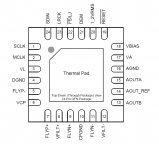
Sorry to refloat this thread, but I've found an HDMI developing board with the AD ADV7513 which is an "old" chip but pretty capable... and as it looks it seems this little board outputs 8 audio channels in I2S signal format, which would be great to extract audio and send it to a DSP, process it and then output it with a high quality DAC.
This is the board:
Placa de desarrollo RGB BT1120 BT656, entrada a interfaz Multimedia de alta definicion, salida ADV7513, placa de solucion de pantalla FPGA|Enrollador de cable| - AliExpress
Also, some pictures of the data sheet.
I know HDMI audio has a high jitter, but still if we can get a DSP with HDMI input, would be great.
Attachments


- Home
- Source & Line
- Digital Line Level
- HDMI DAC to RCA pre amp to DSP to active speaker