Perhaps I'm so tired. Cordell's circuit don't improve any thing. I don't still understand what reason is🙁
Many words, a few deeds
To thanh : Don't be sad Thanh - I will send you schematic of my amp, where is Hawksford's circuit used - look at this and probably you will be understand 😉. Send me your private mail.
To thanh : Don't be sad Thanh - I will send you schematic of my amp, where is Hawksford's circuit used - look at this and probably you will be understand 😉. Send me your private mail.
Re: Re: Lower and higher harmonic components
The things may get different with complex signals but here we rather talk about intermodulation distortion which is sometimes in good, but sometimes in not that good relation with the harmonic distortion of the given device, so that is why it is additionally measured.
Sometimes this move from 60dB (0.1%) toward 80dB (0.01%) distortion can mean move toward better resolution, but there are too much devices with glorious distortion specs yet with marginal subjective resolution. And there are those with 60dB having excellent resolution. Remember, good old analog turntable has dynamic potentials of about 60dB.
WRT the comparison between two devices with different harmonic distortion numbers or different harmonic distortion contents, it is not easy at all to make any meaningful comparison of that kind, simply because you can’t make them to be sure they differ only in one parameter (harmonic distortion), you never know what are the other things involved. Finally, that is why I have uploaded those files. So, you take an amp with THD of 0.00000x% and play them.
Of course, possible relations between the spectrum of harmonic distortion and some other properties/parameters is another topic.
Pedja
millwood said:they sounded absolutely the same to me. I suppose it would be even harder if the "base" signal is real life music (or noise).
jarek said:This is a very good example to remind us where we are. It gives a accurate distance for discussion on what figures of THD are important. I have heard 0.1% and not 0.01% - with single ton. With mixed I would have a trouble with interpretation.
Yes, me too have big problems to hear that -80dB. When mixed with 0dB I couldn’t normally distinguish -60dB from -80dB, nor would I have a clue if they are here at all. It is important to understand that 80dB is tremendous ratio, something like the difference between a silent speech and noise of the big airplane in close proximity.PMA said:Jarek,
this is a single tone. Consider real complex music and the new distortion products created. Very different from the single tone test. Remember what I spoke about - audibility of single tone through the amplifier with distortion of 0.05% spread to high harmonics.
BTW - what is the distortion of your amplifier, is not it higher than 0.01%?. To declare any conclusions, you must have possibility to compare several designs in one time.
You will recognize 0.003% distortion at high harmonics on the real music - that's what I have meant.
The things may get different with complex signals but here we rather talk about intermodulation distortion which is sometimes in good, but sometimes in not that good relation with the harmonic distortion of the given device, so that is why it is additionally measured.
Sometimes this move from 60dB (0.1%) toward 80dB (0.01%) distortion can mean move toward better resolution, but there are too much devices with glorious distortion specs yet with marginal subjective resolution. And there are those with 60dB having excellent resolution. Remember, good old analog turntable has dynamic potentials of about 60dB.
WRT the comparison between two devices with different harmonic distortion numbers or different harmonic distortion contents, it is not easy at all to make any meaningful comparison of that kind, simply because you can’t make them to be sure they differ only in one parameter (harmonic distortion), you never know what are the other things involved. Finally, that is why I have uploaded those files. So, you take an amp with THD of 0.00000x% and play them.
Of course, possible relations between the spectrum of harmonic distortion and some other properties/parameters is another topic.
Pedja
If this may be useful, here are the analyzed files I have posted in the post #151.
And the file from the post #157.
An externally hosted image should be here but it was not working when we last tested it.
And the file from the post #157.
An externally hosted image should be here but it was not working when we last tested it.
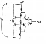
Looks like voltage error sensing circuit.
Might been a signal splitter if the signal input was in between emitters of the transistors on the left side.
Might been a signal splitter if the signal input was in between emitters of the transistors on the left side.
Nelson Pass said:I'll give you a hint. It's a bias circuit for a complementary
follower output stage.
Hmm. Looks like a combination of temp compensated bias with the split collector resistors and some sort of current limiting. Then again, that part might also double as a Hawksford error correction circuit, depending on the resistor values.
Then again again, his may also be a novel circuit to de-ionize a listening room to remove listener bias...
Jan Didden
Nelson's circuit is from his 1976 patent. Hawksford's error correction circuit is derived from Nelson's circuit.
I think the point Nelson is making is that he tried these kinds of circuits 30 years ago. For him they were interesting for a while, but now he no longer uses them. I would assume that this is because, in his experience, they don't sound as good in the real world as one might think based on simulations or measurements.
I think the point Nelson is making is that he tried these kinds of circuits 30 years ago. For him they were interesting for a while, but now he no longer uses them. I would assume that this is because, in his experience, they don't sound as good in the real world as one might think based on simulations or measurements.
If this circuit reduce crossover distortion better than other circuits, sound must be better too. But Nelson now like " musical stove " 😀 .
Upupa Epops said:If this circuit reduce crossover distortion better than other circuits, sound must be better too.
Perhaps you are right. But I don't think so. I will put my faith in my own experience, plus that of Pass and Curl.
Charles Hansen said:
Perhaps you are right. But I don't think so. I will put my faith in my own experience, plus that of Pass and Curl.
There is no substitute for ones own experiance...
Charles, it's neverending discussion - you, and Nelson too, both like " adequate distortion " and you both know, how it in yours mind give reason. In both products ( in your and in Nelson's too ) I hear in forte distortion, which I don't like - I like " distortionless " amps 😎 . When will be on market speakers with realy low distortion ( and this age is comming ), future judge as 😉 .
I think it's still an open question. One would like to think
that a truly distortionless amplifier would have the best sound,
but I assume that would be under conditions where the rest
of the chain is ideal. If the rest of the chain is not ideal, there
is always room for an argument that some distortion
complements or masks some other, making the overall sound
better.
BTW, you win Charles. I was scanning a 30 year old notebook
into computer files, and couldn't resist. 😎
Upupa Epops said:
.... When will be on market speakers with realy low distortion......?
As close as it gets....:
http://www.bwspeakers.com/index.cfm/fuseaction/products.models/label/Model Nautilus
Nelson Pass said:
One would like to think
that a truly distortionless amplifier would have the best sound........
It should...in principal, if only its power supply would back it up.......
People tend to forget that the power supply actually drives the loudspeaker, with the electronics providing modulation....
No point in having low THD circuitry, if the power supply breaks wind as soon as the going gets tough....
WHAT'S IN A NAME...
Hi,
If the PS wouldn't back it up would it then not distort ?
IMHO if it really is absolutely devoid of all sorts of distortion it would stand a chance to make such a claim.
Untill that day it's back to the cooking pots and hopefully we'll come up with a good recipe.
Cheers,😉
Hi,
It should...in principal, if only its power supply would back it up.......
If the PS wouldn't back it up would it then not distort ?
One would like to think that a truly distortionless amplifier would have the best sound........
IMHO if it really is absolutely devoid of all sorts of distortion it would stand a chance to make such a claim.
Untill that day it's back to the cooking pots and hopefully we'll come up with a good recipe.
Cheers,😉
Re: WHAT'S IN A NAME...
...not the circuits fault though ...is it.....??
answer: Build a more robust supply...
fdegrove said:Hi,
If the PS wouldn't back it up would it then not distort ?
...not the circuits fault though ...is it.....??
answer: Build a more robust supply...
- Status
- Not open for further replies.
- Home
- Amplifiers
- Solid State
- Hawksford