Hi Thanh,
You need to explore MOSFETs and savour their seductive advantages! They have much superiority more than boast!
Why is your design needing error correction when regular NFB techniques can give you vanishingly low THD? You must ask yourself this.
Cheers,
Greg
You need to explore MOSFETs and savour their seductive advantages! They have much superiority more than boast!
Why is your design needing error correction when regular NFB techniques can give you vanishingly low THD? You must ask yourself this.
Cheers,
Greg
thanh said:Hi Jorge ! Have you built this circuit ? what's about result ?🙂
Hello, Thanh
No, I haven't build it. First I need to do a layout, then order PCBs...
amplifierguru said:
Why is your design needing error correction when regular NFB techniques can give you vanishingly low THD? You must ask yourself this.
Hello, Greg
Interesting point.
Lots of NFB will not linearise crossover distortion, and this proves it's not the universal panacea.
So, looking at how much an error correction costs (specially if one already have 2 transistors in the bias circuit), why not to use it?
Besides, it helps a lot with crossover disto...
Then apply lots of NFB to a blameless layout.
Cheers,
Jorge:
If it is primarily crossover distortion that you want to eliminate (or at least markedly improve), you don't need anything as elaborate as a Hawksford-style error correction circuit.
To mention a possible starting point, even one of the early Marantz transistor power amps (I think it was the Marantz 15 from 1968) had an output stage that ventured in this direction.
hth, jonathan carr
JORGE
"Lots of NFB will not linearise crossover distortion"
Sorry, misconception. NFB linearises crossover distorsion as it linearsies any non-linearity in the fb loop. Just it can't completely remove it as it necessarily has a limited amount.
~~~~ Forr
§§§
"Lots of NFB will not linearise crossover distortion"
Sorry, misconception. NFB linearises crossover distorsion as it linearsies any non-linearity in the fb loop. Just it can't completely remove it as it necessarily has a limited amount.
~~~~ Forr
§§§
For well known reasons, global NFB will not eliminate very high order harmonics created by cross-over distortion. What is worse, global NFB creates new high order harmonics, that were not present before application of global NFB. This we have explained many and many times, probably without any success.
PMA
"global NFB creates new high order harmonics, that were not present before application of global NFB."
Even without NFB, any non-linearity, giving intermodulation, adds harmonics not present in the input signal. See Peter Baxandall's papers on the subject of NFB. This is one the first thing to do when speaking about NFB and harmonics.
~~~~~ Forr
§§§
forr said:JORGE
"Lots of NFB will not linearise crossover distortion"
Sorry, misconception. NFB linearises crossover distorsion as it linearsies any non-linearity in the fb loop. Just it can't completely remove it as it necessarily has a limited amount.
~~~~ Forr
§§§
Ok, will not reduce enough...
jcarr said:Jorge:
If it is primarily crossover distortion that you want to eliminate (or at least markedly improve), you don't need anything as elaborate as a Hawksford-style error correction circuit.
Johnathan
I my viewpoint is that a Hawksford based circuit is very simple, so why not to use it?
See here:
http://www.diyaudio.com/forums/showthread.php?postid=707953#post707953
Cheers.
Dear Dimitri:
The way that the schematic has been drawn looks somewhat unusual, but Marantz 15 indeed appears to be the design I had in mind, with the diodes in the output stage.
Thank you for your time, and thanks for the link!
best, jonathan carr
The way that the schematic has been drawn looks somewhat unusual, but Marantz 15 indeed appears to be the design I had in mind, with the diodes in the output stage.
Thank you for your time, and thanks for the link!
best, jonathan carr
Really ? but I can'tWhy is your design needing error correction when regular NFB techniques can give you vanishingly low THD? You must ask yourself this.
🙂 Can you help me ?
yes , ok . Although I use current mirror but 2nd,3rd often lower than 10th..,20thglobal NFB will not eliminate very high order harmonics
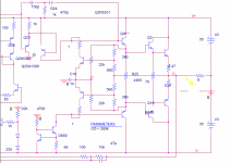
Hi All ! Can my schematic correct distortion ?
impedance output of VAS is 100V/11mA , is it right ?
I tried to simulate with many values of R25 but distortion can't be zero ,in a range of 2mV to 3mV , even higher than without correction circuit
thank you !
impedance output of VAS is 100V/11mA , is it right ?
I tried to simulate with many values of R25 but distortion can't be zero ,in a range of 2mV to 3mV , even higher than without correction circuit
thank you !
Attachments
hi dimitri! thank you very much !
but R1 seem to be =22k // 2200 (1-k) , I used R25 in parallel two 22k resistor .
however thank you very much !
but R1 seem to be =22k // 2200 (1-k) , I used R25 in parallel two 22k resistor .
however thank you very much !
I think that R25 only sets bias of predrivers and has very little to correction itself
The resistors of 1 ohm are probably in inappropiate place: collectors of EC should be joint to bases of predrivers. 1 ohm is very low value too 😉
try to experiment rather with 22k resistors than R25 and parallel with two 560R thete should be a biasing pot.
regards
The resistors of 1 ohm are probably in inappropiate place: collectors of EC should be joint to bases of predrivers. 1 ohm is very low value too 😉
try to experiment rather with 22k resistors than R25 and parallel with two 560R thete should be a biasing pot.
regards
Oh! Which is Q9 or Q2 pre-driver tst ? I'm in trouble in its namecollectors of EC should be joint to bases of predrivers
thanks ! Because orcad pspice cant' know variable resistortry to experiment rather with 22k resistors than R25 and parallel with two 560R thete should be a biasing pot
Hi dimitri ! There are no good result ,
Perhaps that formula can only be used in the Hawkford 's schematic which has no R25 .,
Are there any one like Halcro's schematic ? I'm studying his schematic but it is too hard
Perhaps that formula can only be used in the Hawkford 's schematic which has no R25 .,
Are there any one like Halcro's schematic ? I'm studying his schematic but it is too hard
Hi Thanh,
I agree - and for what. I reckon he's lost the plot, personally. My 'Simple Killer Amp' with a good chip front end can do 0.0001% THD on a 2" x 4" board so what's so special with Halcro. I'd be happy to A/B with Halcro publically double/blind.
Mine has 140 dB PSRR so how's the numbers race!
Cheers,
Greg
I am wondering why some of undoubtly GREATEST and most experienced audio designers like Greg Ball or Pavel Dudek just to name two, spend most time here self-advertising.
😕
😕
- Status
- Not open for further replies.
- Home
- Amplifiers
- Solid State
- Hawksford output error correction circuit?