mike! I don't understand "when clipping to +" . With 700mV pulse signal, output voltage only include "positive part" .hi thanh !
I did some more checkings on the asymamp i posted here, it's kind
of useless. When clipping to + , it completely breaks down, seems
that currentmirror is not too easy. I could remove the buffer, but
this is bad for distortions. BTW, it's nearly identical to the blameless,
not so blameless at all... I would never build an amp showing these
symptoms !
So i will continue finetuning my symamp first.
Mike
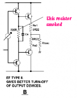
Yesterday, when I turned off the neonlight ,my amp also broke down . V- failured

Attachments
mike! amp which I have just touch upon was modified with 3.3k collectorresistor in diffstage and increased current source .Orcad say thay open-loop gain is 55 ,not 55.000 . What fool orcad is😀
hi lumanauw !
hmm, the output with my circuit is not inverting... 🙂
I am not sure how you want to use the currentmirror, can you show
some schematic ?
I use complementary diffamp, resistorloaded, and then symetrical
folded cascode. As i use negative side of diffamp, output is not
inverting. I can post schematic later.
hi thanh !
Not nice to hear you blew your amp... Did the PSU fail ?
What kind of amp was this ?
With clipping to +, i meant when reaching max positive voltageswing
where it should clamp, it breaks down to 0 volt until level drops again
below clippingthreshold.
I don't understand what you mean with openloopgain = 55 ?
Closedloop is 45 with my amp. So openloop should be much higher ?
Did you adjust DC for measuring with openloop ?
3.3k collectorresistor + increased currentsource ? That must be
a giant currentbias in vas ?
Mike
Hi, Mike,
😀 I really forgot, that the signal can be taken from left or right leg of differetial.
Your design is 2 stages class AB! and it has low OL gain too. Should sound good. When will you finish the prototype?
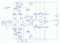
What I intended to use is just like the "benny.jpg" in post #175. Current mirror from one leg of differential as VAS. What do you think?
😀 I really forgot, that the signal can be taken from left or right leg of differetial.
Your design is 2 stages class AB! and it has low OL gain too. Should sound good. When will you finish the prototype?
What I intended to use is just like the "benny.jpg" in post #175. Current mirror from one leg of differential as VAS. What do you think?
Thanks your explanation! I didn't adjust DC when I measure openloop gain because I think that adjusting or without adjusting is not a problem. OPen-loop gain is 55 and close-loop gain is 33hi thanh !
Not nice to hear you blew your amp... Did the PSU fail ?
What kind of amp was this ?
With clipping to +, i meant when reaching max positive voltageswing
where it should clamp, it breaks down to 0 volt until level drops again
below clippingthreshold.
I don't understand what you mean with openloopgain = 55 ?
Closedloop is 45 with my amp. So openloop should be much higher ?
Did you adjust DC for measuring with openloop ?
3.3k collectorresistor + increased currentsource ? That must be
a giant currentbias in vas ?
Mike
thanh said:
Thanks your explanation! I didn't adjust DC when I measure openloop gain because I think that adjusting or without adjusting is not a problem. OPen-loop gain is 55 and close-loop gain is 33
hi thanh !
I makes a big difference, i once forgot it, and suddenly had a OL-gain
of 3...
If the amp is stuck in clipping due to large dc-offset, it can't create a
signal !
Maybe forgot to put the open -input to gnd ?
Is your amp asym or sym ?
I had no reliability problems with my amp, the topology should be safe...
to lumanauw: I think i need a few days for the prototype.
I need to check your circuit, can't say much yet...
Mike
hi !
I think, this circuit is a normal 3 stage, just one diode to reduce
gain in the diffamp. This should behave normal like a 3stage.
You have 2 active bjts in the vgainstages,the diode not counted.
You ensure with this circuit that current in vas is identical to
current in diffleg.
With the folded cascode i posted, you have one 1 active bjt in
the frontendloop. (per side, top/bottom)
Now i understand why i didn't understand you... 😀
But its still a nice circuit !
Mike
Hi MikeB & lumanauw,
very interesting to see that you've got the same idea about the folded cascode I have some years ago. I can tell you that the folded cascode is an extraordanary stable design and it works very nice in reality. To my opinion it's the best bipolar design available.
very interesting to see that you've got the same idea about the folded cascode I have some years ago. I can tell you that the folded cascode is an extraordanary stable design and it works very nice in reality. To my opinion it's the best bipolar design available.
It looks very good. I'd lower R5 to about 330R and use a 2SA1930/2SC5171 for Q6-Q9. I'd also modify the bias circuit with Q5 to a double transistor design. Increase R18 - R21 to about 330R. And do not forget glue (necessary!) Q10 and Q11 as well as Q12 and Q13 together. Or use better a dual transistor like 2SA1249/2SC3381 for it. I'd also increase R12 and R13 to about 0.22R.
Hi, Mike,
I've got a feeling that R10 and R11 has a low limit. Cannot make lower than a certain value, because it will ruin the constant current properties set by Q15-16. How low can this R10+11 can go? It has something to do with rail efficiency.
Hi, Bocka,
Whats the sound like? I mean compared with ordinary 3stages power amp?
thanh said:mikeb! My amp is a sym amp. It is similar to your amp .
hmm, now i feel double sad about your amp having blown... 🙁
What are the differences ? Have you found why it blew up ?
Maybe you also used the sj74 ? It has a max-rating of 25volt.
What transistors did you use in vas and predriver ?
Mike
lumanauw said:Hi, Mike,
I've got a feeling that R10 and R11 has a low limit. Cannot make lower than a certain value, because it will ruin the constant current properties set by Q15-16. How low can this R10+11 can go? It has something to do with rail efficiency.
Hi, Bocka,
Whats the sound like? I mean compared with ordinary 3stages power amp?
Hi lumanauw !
The folded cascode seems to be very flexible, the voltage for the
cascode and these resistors set the current for the "vas". I choose
~2ma, but other values did not have very big effect on the circuit.
I think the larger the current, the lower the gain.
I will start building a prototype this evening...
Mike
I use all bjt no jfet. I can't buy jfet. Diyers don't like jfet in my country. It has a max-rating of 30V .MikeB said:
hmm, now i feel double sad about your amp having blown... 🙁
What are the differences ? Have you found why it blew up ?
Maybe you also used the sj74 ? It has a max-rating of 25volt.
What transistors did you use in vas and predriver ?
Mike
Last night, I adjusted the collectorresistor -->offset voltage is 66mV and max O/L gain is 150 .
- Status
- Not open for further replies.
- Home
- Amplifiers
- Solid State
- Have you ever succeed in buiding a input stage with current mirror?