That other impulse response is intriguing and although 'similar' in appearance is somewhat different in what it is showing.
The first thing to note is that the impulse response itself is inverted. This isn't a concern, but take a look at the reflections.
In your measurements you have a reflection starting at around 2ms that goes peak dip peak. If you invert this, as the other measurement is, we should get dip peak dip, but we don't we're still seeing peak dip peak, so they aren't quite the same thing.
You can also see that the time when this reflection occurs is different compared to yours.
This is mildly interesting imo and could simply be that the mic position was slightly different or something.
I would be interested in seeing a near field measurement with the microphone at the edge of cone, say 2cm in from the surround and the mic about 1cm from the cone itself.
I noticed that too, but if you look through that other thread, the frequency response results of them look a whole lot like what I'm seeing. It isn't easy to read, because the 10-15 pages discussing this have a lot of image-heavy posts that are barely related mixed in. I'll try measuring where you suggest, maybe overlay that with ~2cm from the phase plug?
Yeah a measurement close the phase plug would be nice also. I don't think the phase plug will be causing this, it could be path differences between the edge of the cone and the phase plug, but the plug itself is too small to properly reflect sound at 1-3khz.
I went through and read some of that post and they pretty much went through and eliminated all the things I'd try and eliminate from being traditional causes. John Ks explanation makes the most sense, three very closely related resonances that happen to sort of cancel each other out earlier on in the impulse response, hence they are not seen, then they go out of sync with one another and appear later on as individual resonances.
This is unfortunate and it clearly indicates that you want to use this driver as low as the tweeter will go.
I did originally think of resonances as the sound travels up and down the cone but these tend to 'ring' so would be present right from the start and propagate through the cone a lot faster then the speed of sound. Having a few different resonances interfering with one another such that they partially null one another at the start of the impulse, but then fall out of sync and cause a peak later on is certainly quite atypical but you can always rely on john k to come up with a reasonable explanation and with scientific data to prove it.
Okay, so we are back to page 2 completely now 🙂. What I was thinking at that point is that I would take a good nearfield, then experiment with farfield measurements until I have one that has no additional mess introduced with a useable gate, and then design the crossover with that, midrange ripple and all. Do you agree? There is no way to damp this electrically, is there?
Oh yeah, and I guess I might as well try those distortion measurements. May come in handy for the HF driver here. What measuring distance would you suggest for those?
Oh yeah, and I guess I might as well try those distortion measurements. May come in handy for the HF driver here. What measuring distance would you suggest for those?
Last edited:
There is no way to electrically damp this unfortunately however! John K mentioned that this was occurring because of 'beating' effects. Now if you're not clear on what beating is it's when you combine say a 25khz tone and a 26khz tone, you cant hear either of those, but the two waves combine and produce a tone at 1khz. Now its possible that the peaks appear as the result of higher frequencies combining. I don't recall John K mentioning what frequencies it was that he had to combine to get the result he produced in that thread though. But lets say the wiggle at 2khz came about by an effect occuring between a 4 and 6 khz tone as they rippled through the cone, naturally if the 4 and 6khz stuff is filtered out the 2khz peak wont appear. This is only a long shot mind you and you'd have to measure to find out.
ARTA will enable you to do a test at a sampling frequency of 8000hz. This will effectively limit the bandwidth to 4khz but it should let you see if the 'reflections' in the impulse are affected in anyway too.
ARTA will enable you to do a test at a sampling frequency of 8000hz. This will effectively limit the bandwidth to 4khz but it should let you see if the 'reflections' in the impulse are affected in anyway too.
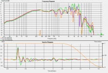
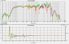
First up for today's measurements: nearfield and nearfield-ish on-axis, nearly un-gated. I was not sure how to best manipulate these for comparison, as far as magnitude and time zero.
Un-gated really means completely opening the gate. You're still gating this quite heavily to around 4ms which is limiting your low frequency resolution to around 300hz.
A real ungated measurement would take the gate out to like 80ms such as in the attached image. This gives you accuracy down to 12hz. Near field measurements are typically used to give you great accuracy at low frequencies, but poorer accuracy at high frequencies.
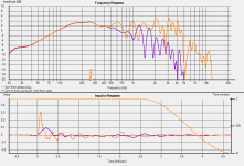
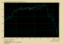
Next up: Edge of cone compared to above. At first glance, this looks like it might be a more pure display of the issue. The ripple is huge, appears to be at a regular 440Hz peak-to-peak, and comes and goes very neatly with gating.
This is actually very interesting to look at as it shows without a doubt that the cone/moving parts are probably mostly responsible for this issue. It is very clear to see that the cones edges do not vibrate at higher frequencies and that the radiating area shrinks as frequency increases. This is why the response drops off because the edge of the cone simply isn't vibrating as much at higher frequencies. This also forms a sort of low pass, which is why the impulse response doesn't have the sharp peak that it displayed before, because the high frequencies and thus the wave lengths with the fastest leading edges have been removed from the measurement. It also shows that the ringing is also associated with the inner regions of the cone as the impulse response has far less stored energy from the measurement done at the cones edges. You could also say that the cone appears to act reasonably pistonically perhaps up to around 450hz as the outside of the cone is still keeping up with the inside.
Attachments
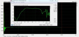
The limitations of a near field response is with capturing the higher frequencies accurately and this gets worse the larger the driver is.
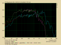
As an example here's the far field measurement of the driver shown in my above post. The higher frequencies of the two are not even close to being similar

As can be seen though the short gate applied here limits the low end resolution to around 600hz.
What you need to do now is take a nice far field measurement, at least 1 meter away, that is reflection free to allow for at least a 3ms gate. This will give you accurate measurements of what the upper part of the driver is doing and will include the delayed resonance issue.
As an example here's the far field measurement of the driver shown in my above post. The higher frequencies of the two are not even close to being similar
As can be seen though the short gate applied here limits the low end resolution to around 600hz.
What you need to do now is take a nice far field measurement, at least 1 meter away, that is reflection free to allow for at least a 3ms gate. This will give you accurate measurements of what the upper part of the driver is doing and will include the delayed resonance issue.
Attachments
I guess what I meant is that it's gated beyond where any major new response features will appear. Here's the same thing with no gate at all. Any requests for new things to try? I'm not sure what I'm doing next here at the moment. edit: oh yeah, I was gonna try low vs high sampling rate - I'll do that.Un-gated really means completely opening the gate. You're still gating this quite heavily to around 4ms which is limiting your low frequency resolution to around 300hz.
I just realized that when you've got an image zoomed, you can hit up and down to scroll through all the image attachments on the same page. That's neat.
Attachments
Last edited:
Yeah that's a lot better, now you're getting good low frequency data, but there's still a surprising amount of jaggies/ripples. You also appear to be letting in quite a lot of noise when you open up the gate. Does Holm have an averaging function where it will take the measurement 10 times or so and then average them out? I find this works extremely well to reduce/eliminate the noise that the mic can introduce.
I have to say though, I do find ARTAs interface a lot easier to actually manipulate compared to HOLM. I tried Holm a while ago and thought that it was decent as it did what ARTA did, but a right faff as it made things harder to do then they needed to be.
I have to say though, I do find ARTAs interface a lot easier to actually manipulate compared to HOLM. I tried Holm a while ago and thought that it was decent as it did what ARTA did, but a right faff as it made things harder to do then they needed to be.
I am preferring ARTA too. I was using HOLM there because it was convenient for outputting the graphs that I wanted in one shot. Anyway, it turns out my hardware and or drivers will not go below 44.1k for the sample rate, so that experiment's out. I could wire up an actual low pass, but I guess that wouldn't be the same.
Here's a 30 cm measurement gated, almost ungated, and the untitled green line happens to be around the max the fft size allowed. I should really figure out what's giving the pre-impulse nonsense in HOLM - still no sign of it in ARTA (unless you count the little dip, which I have another thread about - it's in all my measurements and remains a mystery).
edit: whoops I forgot to mention, this one is averaged 3 times. I tried 6 with no differences, so did not go higher. This is a long log sweep. For short sweeps, I have seen differences persist up to 10-15 averages.
Attachments
Last edited:
I think you can just stick some blue tack in the middle of the spider axi-symmetrically the measure. I am sure you will find a big difference.
As good as the sweeps can be they are not typically suited to making frequency response measurements. They do work of course, but try using the MLS stimulus instead as that's what its designed for.
I don't notice going beyond a few averages does much either, but its definitely worth using some.
Using a low sampling frequency or applying a low pass is really just a pie in the sky idea and it would be interesting just to see it if makes any difference, I doubt it would but you never know 😀
With regards to your crossover I would certainly opt for a 1200hz xover and a 4th order acoustic target too. The driver starts to show issues around these frequency so its lucky the tweeter can just about go that low. A 4th order at 1200hz will put the FR -6dB down here so will definitely help keep the ragged stuff more under control.
Well, I can certainly try that for you soongsc. Do you mean just a dot of it, a short line, or a full circle?
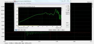
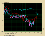
5th Element, is this what you had in mind for Steps? It looks, um, good. The 2nd harmonic is basically the frequency response.. I left all the settings on default, 1/24 octave. It's only 0.85VAC at 1kHz. I guess I'll have to get out the earplugs if I need to go louder.
5th Element, is this what you had in mind for Steps? It looks, um, good. The 2nd harmonic is basically the frequency response.. I left all the settings on default, 1/24 octave. It's only 0.85VAC at 1kHz. I guess I'll have to get out the earplugs if I need to go louder.
Attachments
Last edited:
I thought the sweeps were far less sensitive to distortion and environmental noise? Anyway, I used both a lot when I was first setting this stuff up, and never saw any more than an occasional fraction of a decibel difference here and there.As good as the sweeps can be they are not typically suited to making frequency response measurements. They do work of course, but try using the MLS stimulus instead as that's what its designed for.
Yes that is what I was talking about with regards to STEPS and you can clearly see the ringing effect of the cone take a hold of the distortion performance. The second order basic follows the frequency response profile and you can see the distortion suddenly reduces as the cone or whatever it is, stops ringing. 1% 2nd order though though is still pretty high in level for a drive level of only 0.85Vrms, granted this is a sensitive driver so it's going to be loud, but could you repeat the measurement with the mic preamp turned down a bit or with the mic further away, it's possible that you're mildly clipping it or pushing it a bit too hard.
The same is true for the higher harmonics too except these are happening at integer multiples below the fundamental. In other words the cone stops ringing at around 4khz and if you divide 4 by 3 you end up with 1.3khz and as you can see the third order also plummets somewhere around 1.3khz. The 4th and 5th order products also do the same thing. Quite clearly the motor on the TD15M is quite linear and the soft parts would appear to be the limiting factor.
The same is true for the higher harmonics too except these are happening at integer multiples below the fundamental. In other words the cone stops ringing at around 4khz and if you divide 4 by 3 you end up with 1.3khz and as you can see the third order also plummets somewhere around 1.3khz. The 4th and 5th order products also do the same thing. Quite clearly the motor on the TD15M is quite linear and the soft parts would appear to be the limiting factor.
- Status
- Not open for further replies.
- Home
- Loudspeakers
- Multi-Way
- Has anyone here measured a TD15M? (I have them)