Wizards being known as retainers of knowledge I hate to second guess but I'd like to put it on my first build instead of the standard 68 rainbow.
HIs logic is:

HIs logic is:
Are you talking about guitar amplification, isn’t it?
You can also directly use 33k and you’ll be fine.
You can also directly use 33k and you’ll be fine.
There is also a Miller effect so the input capacitance is increasing adding another capmy first build instead of the standard 68 rainbow.
The ax7 has 1,7 pf as grid to plate if the gain is, p.e., 70 the input cap is 120 pf, if you add another value you will have a low pass filter with the R in series to grid
The frequency response will vary if you change these values and, maybe, you can get a right combination for a good sound
Guitar input stages gain ranges from -60 to -75, so 100 to 120pF is the capacitance to consider depending on the plate resistor (tipically 100 or 220k). Marshall added a 47-100 pF cap between plate and cathode, manu others pre-equalize the sound.
I’ve always used 33k on instrument amplification, but the 10k + capacitor to ground can be used as well. Just consider the signal is supplied by a medium impedance pickup, so there’s an interaction with it.
As a first rule of thumb, you divide the grid stopper by 6,8, then you have to get a total capacitance of 6,8 times the initial, so a total around 680-820 pF, that with a low impedance driver would mean adding 560-720 pF from grid to ground. But again, the pickup will interfere, so lower values are fine as well.

I am not yet at a "stage" where math is being used currently I am follow schematics. Hopefully I can learn why these things work eventually but with my brain being math-dumb not looking good boys,
It's very easy to calculate frequency response if you have a half decent calculator by using this formula - 1/(6.28 x C x R) or you can sub f (frequency) for either R or C. An easy example, what's the cut off frequency of a 1k2 cathode resistor & 47u bypass cap? 1/(6.28 x 1200 x 0.000047) = 2.82hz or what cap do we need forv a cutoff frequency of 15hz, same resistor - 1(6.28 x 1200 x 15) = 8.8u or a 10u will do.
In the case of a grid stopper the R is your grid stopper & the C is the inter electrode capacitance of the valve x by the gain of the stage. Once you've done a few calcs, it's less scary. Easier to test though on an actual stage using a scope. There are also numerous electronic calculators online too.
Andy.
@Diabolical Artificer
normally it is like that, but with instrument amplification the source is a medium impedence inductor with capacitors in parallel.
If you drive the stage with a low impedance source, lab and real results will differ.
Here you can find some info: https://sound-au.com/project214.htm
normally it is like that, but with instrument amplification the source is a medium impedence inductor with capacitors in parallel.
If you drive the stage with a low impedance source, lab and real results will differ.
Here you can find some info: https://sound-au.com/project214.htm
Andy, I appreciate the thoughtful response, but understand that math is not my strong suit. Since my brain does not follow naturally it would take a lot of patience (and time) to teach myself the math required to follow the underpinnings of what I'm doing. Although in theory I'd love to.
Thanks for clarifying Mr Zed, as you say your bog standard guitar isn't a perfect source, the PU could be a humbucker or single coil followed by a long lead.@Diabolical Artificer
normally it is like that, but with instrument amplification the source is a medium impedence inductor with capacitors in parallel.
If you drive the stage with a low impedance source, lab and real results will differ.
It isn't mine either, I got a grade 4 CSE for maths at school, which is crap but I had a go using Merlin's site & excellent articles as a guide I manage to stumble through. Fair play to you for trying to learn, you'll get there.Andy, I appreciate the thoughtful response, but understand that math is not my strong suit.
Andy.
Input capacitance of a 12AX7 with fully bypassed cathode resistor could be as high as 200pF.
A 3 meter guitar cable (about 18 feet) will introduce roughly 500pF of cable capacitance shunting to ground.
I don't think you need to add a capacitor from grid to ground at the 12AX7 input.
A 3 meter guitar cable (about 18 feet) will introduce roughly 500pF of cable capacitance shunting to ground.
I don't think you need to add a capacitor from grid to ground at the 12AX7 input.
Thye noise from the 68K may or may not be an issue. This depends a lot on the total gain in the amp, and the type of resistor used.
Science is science, but guitar pickups are often hand wound, or machine wound in a random fashion. Then they are usually potted with something to keep them wound and reduce the microphonic effects of loose wire. This can be anything from wax to epoxy, to nothing at all! Every pickup is different, especially cheap ones.
The Dumm Blonde method is to put a 250K or so pot in between the input jack and the tube and turn it to get the best sound, measure it, then use that value. Try every guitar and cable you have and pick the best compromise. Can't find the best choice for everything? Use two input jacks. You only need one 1 meg resistor to ground. It can be placed at either jack or even at the grid pin of the tube. Pots are usually noisier than a plain resistor, so test with the resistor of the value you choose before soldering. I have found metal film resistors to be the quietest, but that may vary depending on the parts and circuit used. 12AX7's can vary a lot too. Most of my amps have used a small resistor value, 20K or less.
Simulation and calculation works well in HiFi applications where low THD and a descending harmonic profile is the desired criteria. How do you judge or measure "tone" when every guitar player has their own ideal "tone".....or several preferred "tones."
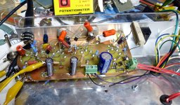
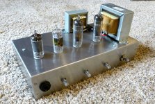
Take your best "first guess" and then tweak to suit the tone. Here is an amp being tweaked with pots, clip leads, and some extra parts. It morphed into a new design on a new PCB layout and now lives in a neat chassis and cabinet.
Science is science, but guitar pickups are often hand wound, or machine wound in a random fashion. Then they are usually potted with something to keep them wound and reduce the microphonic effects of loose wire. This can be anything from wax to epoxy, to nothing at all! Every pickup is different, especially cheap ones.
The Dumm Blonde method is to put a 250K or so pot in between the input jack and the tube and turn it to get the best sound, measure it, then use that value. Try every guitar and cable you have and pick the best compromise. Can't find the best choice for everything? Use two input jacks. You only need one 1 meg resistor to ground. It can be placed at either jack or even at the grid pin of the tube. Pots are usually noisier than a plain resistor, so test with the resistor of the value you choose before soldering. I have found metal film resistors to be the quietest, but that may vary depending on the parts and circuit used. 12AX7's can vary a lot too. Most of my amps have used a small resistor value, 20K or less.
Simulation and calculation works well in HiFi applications where low THD and a descending harmonic profile is the desired criteria. How do you judge or measure "tone" when every guitar player has their own ideal "tone".....or several preferred "tones."
Take your best "first guess" and then tweak to suit the tone. Here is an amp being tweaked with pots, clip leads, and some extra parts. It morphed into a new design on a new PCB layout and now lives in a neat chassis and cabinet.
Attachments
That 68K resistor was in an early Fender amp if I remember correctly. It appears to be copied in many designs as if it was some secret sauce.
This is the most important statement on this entire thread. Guitar amplifiers and high fidelity amplifiers are NOT the same.How do you judge or measure "tone" when every guitar player has their own ideal "tone".....or several preferred "tones."
Many Fender amps had multiple inputs, isolated by a 68K "stopper" resistor to each. One was a shorting type, that grounded that input when unused. The result - the "shorting" connector (marked: High) gave full gain, the other (marked: Low) 6dB less via voltage division, and both connectors gave same (full) gain if two instruments were plugged in. Pickups see 1 meg or 136K, minimal loading. For this configuration, 68K was probably the best choice; for a single input a lower value is fine.
Not the prettiest boards in the world lolThye noise from the 68K may or may not be an issue. This depends a lot on the total gain in the amp, and the type of resistor used.
Science is science, but guitar pickups are often hand wound, or machine wound in a random fashion. Then they are usually potted with something to keep them wound and reduce the microphonic effects of loose wire. This can be anything from wax to epoxy, to nothing at all! Every pickup is different, especially cheap ones.
The Dumm Blonde method is to put a 250K or so pot in between the input jack and the tube and turn it to get the best sound, measure it, then use that value. Try every guitar and cable you have and pick the best compromise. Can't find the best choice for everything? Use two input jacks. You only need one 1 meg resistor to ground. It can be placed at either jack or even at the grid pin of the tube. Pots are usually noisier than a plain resistor, so test with the resistor of the value you choose before soldering. I have found metal film resistors to be the quietest, but that may vary depending on the parts and circuit used. 12AX7's can vary a lot too. Most of my amps have used a small resistor value, 20K or less.
Simulation and calculation works well in HiFi applications where low THD and a descending harmonic profile is the desired criteria. How do you judge or measure "tone" when every guitar player has their own ideal "tone".....or several preferred "tones."
Take your best "first guess" and then tweak to suit the tone. Here is an amp being tweaked with pots, clip leads, and some extra parts. It morphed into a new design on a new PCB layout and now lives in a neat chassis and cabinet.
I mean, this is overly deconstructive, there are maybe two dozen (just guessing) preferred tones as a function of the human ear and the standards of modern music.This is the most important statement on this entire thread. Guitar amplifiers and high fidelity amplifiers are NOT the same.
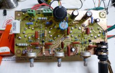
The first board with all the flying parts is somewhat typical of the results I got with the toner transfer method which uses a printout from a laser printer for the etch resist. It was made in Florida with my old HP laser printer. The second board incorporates all of the flying parts into the PC board design. It was made after I moved to West Virginia and got a new Canon laser printer since the HP got damaged during the move. My DIY PCB quality basically sucks with the Canon printer, but I am not going to buy another printer for test boards. Despite the poor quality which required a lot of patching during the build, that amp has worked great for 7 years.Not the prettiest boards in the world lol
This guy has devoted most of his Youtube channel in pursuit of "tone." I'm sure that his "Nashville" version of tone is a bit different than mine which leans toward a blend of surf music from the 60's (pile on the reverb) to classic rock from the 70's (crank the amp till it melts).I mean, this is overly deconstructive, there are maybe two dozen (just guessing) preferred tones as a function of the human ear and the standards of modern music.
- Home
- Live Sound
- Instruments and Amps
- Has anyone had good results with ValveWizard's 68k Input replacement?