Large Audio Companies Always Try To Use Less Components To Get More Profits On Their Products, This Means That They're Reducing Safety Margins On Components, Specially Output Stages, Tiny Heatsinks, Barely Enough Capacitance/Capacitor Quality, Even Tough They Claim Thousands Of Watts Per Channel With Ridiculous Underrated Values On Components And Barely Power Devices Quantity....Better DIY
Large Audio Companies Always Try To Use Less Components To Get More Profits On Their Products, This Means That They're Reducing Safety Margins On Components, Specially Output Stages, Tiny Heatsinks, Barely Enough Capacitance/Capacitor Quality, Even Tough They Claim Thousands Of Watts Per Channel With Ridiculous Underrated Values On Components And Barely Power Devices Quantity....Better DIY
would you know if these so called professional power amps fall under the FTC trade regulations act? what testing method is used if any?
Guess What????
Sound & Communications - Audio
Greetings And Thank You For Reply...
Hope This Answers Your Questions...would you know if these so called professional power amps fall under the FTC trade regulations act? what testing method is used if any?
Sound & Communications - Audio
Greetings And Thank You For Reply...
Thanks Mr. Kimberlator , Mr, Sakis and Mr. Tony,
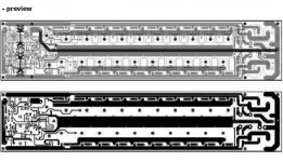
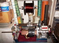
photos of amp I posted are of experimental stage.While wiring real amps I will try to use as thick wire as I could as per your suggestions.Regarding Rod Elliot design all I could get is this unclear picture.can I get clear p.c.b design.
regards
photos of amp I posted are of experimental stage.While wiring real amps I will try to use as thick wire as I could as per your suggestions.Regarding Rod Elliot design all I could get is this unclear picture.can I get clear p.c.b design.
regards
Attachments
Hi Vedmitraa
What Transistors You Will Use On Rod's Amp?
Best Regards...
Hello,Thanks Mr. Kimberlator , Mr, Sakis and Mr. Tony,
photos of amp I posted are of experimental stage.While wiring real amps I will try to use as thick wire as I could as per your suggestions.Regarding Rod Elliot design all I could get is this unclear picture.can I get clear p.c.b design.
regards
What Transistors You Will Use On Rod's Amp?
Best Regards...
well as I told I have 50 pairs of mj 15024 - 15025 with me I want to use them.Even p.cb. of driving circuit will do .plus you trick of baising.
regards
regards
would you know if these so called professional power amps fall under the FTC trade regulations act? what testing method is used if any?
Amps like Pyle don't have FTC ratings. Or even EIA. But nowadays the FTC rating only requires a burn in at 1/8 power with pink noise, and a 1KHz sine wave test (just long enough to make the measurement). Most modern amps will pop breakers, thermal, or both if subjected to the older 1/3 power burn in - and 20-20k at full "rated" power is just a dream.
Amps like Pyle don't have FTC ratings. Or even EIA. But nowadays the FTC rating only requires a burn in at 1/8 power with pink noise, and a 1KHz sine wave test (just long enough to make the measurement). Most modern amps will pop breakers, thermal, or both if subjected to the older 1/3 power burn in - and 20-20k at full "rated" power is just a dream.
i had my doubts, i suspected this much, thanks for confirming....amps with such high power rating will have to employ humongous psu and heatsinks to pass the FTC testing.....
Certainly There's Very Very Few Namebranded Amps That Do What They Claim, I Don't Know, Lets Say POWERSOFT? CAMCO? LabGruppen? But Even For Those Badass Amps There's No Substantial Rules & Regulations About Power Ratings In Their Wide Range Of Technical Tests, So They Can Easily Claim Overrated Parameters On Their Products, And Hell Lets Speak The Truth Between Us, How Many People You Know That Have Any Knowledge About Amp Specs? They Need Just A Thing To Put Sound On Their Speaker System And That's It !!! Very Few People Cares Even About Speaker Impedance.
Just My Point Of View.....
Cheers To Anyone.....
Just My Point Of View.....
Cheers To Anyone.....
Last edited:
as long as we are aware that most power claims are just that, claims, then i guess we are on the ground....the dreamin' goes on.....😀
it is either FTC or it is not.....
it is either FTC or it is not.....
?
"PYLE" Amplifier Will Deliver 1000Watts Per Channel @4R..Hummmmm......FTC Or EIA? Or Both? And Believe It Or Not This Same Issue Applies In A Very Wide Variety Of "NAMEBRANDED" P.A. Amps, Because As The Article Reads "There's No Such Regulations For Professional Audio Equipment" Nice Dont You Think????
Yes, We Are Aware So All People Are, But Not Everyone Know For Sure If "PYLE" Amplifier Will Deliver 1000Watts Per Channel @4R As The Amp States In Its Front Plate, Right?as long as we are aware that most power claims are just that, claims, then i guess we are on the ground....the dreamin' goes on.....😀
it is either FTC or it is not.....
"PYLE" Amplifier Will Deliver 1000Watts Per Channel @4R..Hummmmm......FTC Or EIA? Or Both? And Believe It Or Not This Same Issue Applies In A Very Wide Variety Of "NAMEBRANDED" P.A. Amps, Because As The Article Reads "There's No Such Regulations For Professional Audio Equipment" Nice Dont You Think????
Last edited:
I'm in...!!!
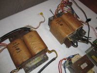
I have two large transformers from QSC amplifiers USA1310 and MX1500
I desire to build a large 500watt 8 ohm amp capable of 4 ohm sub work.
I like Workhorse design seems very roubust... lets continue this was getting intresting.
A posting of Rods revised circuit would be great too.
My transformers hit 95 volts after regulation, would love a great circuit for them.
Pat
Attachments

@ Sir Vedmitraa
Maybe you have done a mistake, as in the pic you have connected 0.22R resistor to the base of the transistor which goes to the output, and 4.7R resistor to the emitter of the transistor on both sides, Kindly check before powering up.
Regards,
Aniket🙂
Maybe you have done a mistake, as in the pic you have connected 0.22R resistor to the base of the transistor which goes to the output, and 4.7R resistor to the emitter of the transistor on both sides, Kindly check before powering up.
Regards,
Aniket🙂
Attachments
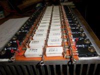
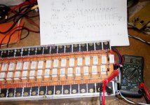
Thanks Aniket for pointing out the fault.that photo is quite old yeah there was this mistake but I rectified that mistake next day.Here is the photo of working amp with 1 ohm load and digital meter connected at output with test tone of 1khz.Meter is showing output voltage.
Attachments
I am not familiar with any instrument at least like the ones shown in the picture that are able to measure correctly anything above 400HZ but may be i am wrong .....
I have used my cheap DMM @ upto and including 50kHz.
I use the comparison method when ever I need good accuracy and/or repeatability.
If I set up an input attenuator that exactly cancels the gain of the amplifier under test, then I can compare the input voltage before the attenuator with the output voltage after the amplifier.
I am comparing DMM Vac readings that are the SAME voltage and the SAME frequency.
If the DMM tells me the voltages are the same, then I believe it. Even when I know that the DMM is decades outside it specified operating frequency range. eg, the input could be set to read 2Vac at 200Hz and at 900Hz, but might read 1.4Vac at 10kHz and 525mVac at 50kHz.
Last edited:
Well I am not that much in theories but when measured with this meter it gave me 66 volts on 100hz ;61.4 volts on 1khz and 52 volts on 20 khz;on 1 ohm load at output signal voltage 1volt with my signal generator on sine wave and rail voltage 90-0-90 on load.
works I have been doinng
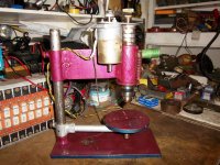
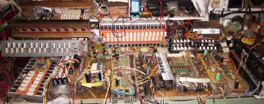
Thanks to all seniors in diyaudio because of them i could do this work ,some of my works photos,please see my page at facebook for more photos.
Vedmitra Sharma
Thanks to all seniors in diyaudio because of them i could do this work ,some of my works photos,please see my page at facebook for more photos.
Vedmitra Sharma
Attachments

- Status
- Not open for further replies.
- Home
- Amplifiers
- Solid State
- Has any one built this 1KW amp?