That's why I made the suggestion.
You need to start eliminating things.
I would start be ensuring proper fusing and swapping the transformers over. That'll tell you if the problem is with the transformer or the amp/PS
...Yes..thanks Ray...I know you were quick to suggest that! 🙂
How would I go about determining size of said fuse...and would it be board mounted...panel mounted...or float free in-line (with one side of the A.C. feed I'm assuming)
...Aaagghh...there I go again making assumptions!!
Hello .. in this model of build the sec are not fused, you could have a shorted bridge rec diode, does happen. unplug the sec connections from the main psu board, if the fuse still blows pretty much 100% faulty transformer .. my bet is the fuse will not blow with the sec connections disconnected unless the transformer is already damaged. When I make my amps I always fuse the sec winding
Will try this now (ish).....plug fitted with 3A fuse BTW??
Hi , i would recommend to disconect secondaries from board, and connect transformer to mains not directly, but through incadescent lamp. If transformer iš good, would not consume high current on primary ,lamp will not lightup. Also can measure output voltages ,and voltage after lamp . User 100w or more rated lamp.
At least , you can try this : disconnect secondary windings from amplifier ,leave connected only mains winding , which is connected to power swith ,mains fuse etc . It has higher resistance ,maybe few ohms . Secondary winding will have less than 1 ohm i think , disconect them . Try to turn on with smaller rating (1-3 amp ) fuse, it should not blow if transformer is ok .
OK....just got back...and tried powering up with 2ndary windings disconnected
...3A fuse went immediately...tried twice...so transformer is gone!
Before I go and replace it.....would I look at rectifier next??
...3A fuse went immediately...tried twice...so transformer is gone!
Before I go and replace it.....would I look at rectifier next??
Also one bad idea... Are you sure ,transformer is proper voltage primary winding rated? Not 120v for usa ,Japan ,etc , but 220-240v ? If fuse blows, then its bad situation . In some cases its possible to rewind,but easier to replace ofcourse.
Also one bad idea... Are you sure ,transformer is proper voltage primary winding rated? Not 120v for usa ,Japan ,etc , but 220-240v ? If fuse blows, then its bad situation . In some cases its possible to rewind,but easier to replace ofcourse.
Well ....it's an ILP 73033...and I just found reference to it in an old '87 ETI
Says it's a 50 50 300VA...RMS current 3.00 (amps?)
...so looks like it was the right one for the job here in the UK
If specification ensures proper voltage for primary ,then it has probably burned primary winding and this causes fuse to blow . Toroidal transformer should consume very little power if unloaded, just few wats. Replace transformer then ... Yes ,its 50v two secondaries 3.0 Amps rated .
Most problem in amplifiers is output transistors shorted ,and no fuses after rectifier present ,so mains fuse blows then ,but transformer gets overloaded hard until fuse blows . But if fuse is replaced to over-rated value ,then result is like this . Fuse should never to be replaced to higher rating if it continues to blow . Yes , i would check rectifier and big capacitors for shorting ,sometimes diode bridge gets one of diodes shorted ,and then you may damage new transformer .
You wrote about a mains fuse - can you solder two wires to blown fuse ,and connect a 100w+ incadescent or halogen lamp to those wires ,and put this in fuses place ? It will protect new transformer while you will repair amplifier .
I think you need to be asking yourself 'why did the transformer fail' as it's unlikely that it would do so unless physically damaged or over-stressed (heat will damage the enamel insulation on the windings causing a short). If the transformer isn't physically damaged you need to find out if the cause of it being over-stressed is still present otherwise you might end up with a replacement transformer in the same state. First thing is to arrange for the correct fuses to the secondaries before using a replacement.
Agree completely . If fuses not present , add them . Check output transistors, rectifier. I'm doing this when repairing amplifier,after transistors replacing :
1. DC output voltage ,going from rectifier to amplifier, connect through small power rated resistor like 10ohms 0.25w , also you can calculate current consumption if amplifier works ,but no signal.
2. Measure DC voltage at amplifier outputs, can be in range few millivolts,for some amplifiers more like 10mv.Adjust if needed.
3. Measure idle current of output transistors and adjust if needed.
4. Apply some signal with speakers connected, but not loud, remember small power resistors may burn. If all ok ,and resistors not smoke, can test with smaller value ones ,or with fuses . Maybe i'm wrong somewhere or missed something, also to connect scope to output would be usefull.
I think you need to be asking yourself 'why did the transformer fail' as it's unlikely that it would do so unless physically damaged or over-stressed (heat will damage the enamel insulation on the windings causing a short). If the transformer isn't physically damaged you need to find out if the cause of it being over-stressed is still present otherwise you might end up with a replacement transformer in the same state. First thing is to arrange for the correct fuses to the secondaries before using a replacement.
Exactly...something has caused this!
Will be looking at rectifier (Diodes x 4??)...see if one 'of 'em is defective...I can do that with my meter!! 🙂
Agree completely . If fuses not present , add them . Check output transistors, rectifier. I'm doing this when repairing amplifier,after transistors replacing :
1. DC output voltage ,going from rectifier to amplifier, connect through small power rated resistor like 10ohms 0.25w , also you can calculate current consumption if amplifier works ,but no signal.
2. Measure DC voltage at amplifier outputs, can be in range few millivolts,for some amplifiers more like 10mv.Adjust if needed.
3. Measure idle current of output transistors and adjust if needed.
4. Apply some signal with speakers connected, but not loud, remember small power resistors may burn. If all ok ,and resistors not smoke, can test with smaller value ones ,or with fuses . Maybe i'm wrong somewhere or missed something, also to connect scope to output would be usefull.
Whooaaa!!...much of this is beyond me!
Baby steps for me...
I know how to do the offset voltage at the speaker out....funnily enough...I've got a reading of 10mv on the other monoblock! 🙂
Wanna baby steps ? Ok ,i will try 🙂 Locate faulty components ,like shorted transistors ,diodes , and replace them all .
1. Dc rectifier ,where 4x diodes and 2 big capacitors ,has its outputs , lets say +60v , gnd , and -60v . I don't know this amplifer ,but lets say voltages can be like those . So those 3 wires are going from rectifier board to amplifier board , you need to disconnect those two ,except ground , and connect them through resistors , you will need two resistors . If resistors not smoke ,continue to step2.
2.No input signal to amplier ,just silence ,speakers not connected yet ,amplifer can produce small dc voltage ,measure it at output of board .Most amplifers have dc protection relay ,so you need to measure before relay contacts ,directly after amplifier output itself ,not on output connectors ,where you connect speaker wires ! Protection circuit may detect dc ,if amplifer is still faulty ,and not turn on that relay ,so you will see no dc voltage at speaker connectors .Some amplifiers have potentiometers ,that allow to balance them ,minimise that dc voltage .
3.Measure dc drop voltage at those 10ohm resistors , and by using ohms law , calculate approx current .Depends on amplifier class ,AB class can draw approx 50-200 ma per output transistors pair .One pair means one transistor going from +60v and one from -60v .If there are 2 outputs transistors on single channel ,then it may be in such range . Sometimes transistors are paralleled , i saw 4 transistors in photo ,so it looks like current consumption would double then .But correct way to measure idle current and adjust is to have schematic or service manual .Typically idle current calculated by measuring voltage drop on low resistance resistors ,going from amplifiers output ,to output transistors ,like 0.22 - 0.47 ohm and to use ohm law to calculate current , knowing resistors resistance and measured voltage drop . Can't answer right now how much current should be correct ,don't know this amplifier .
4.don't connect speakers yet ,but test with some music ,or sine wave , slowly increase volume .Watch resistors ,if they not smell smoke .If smell, turn off , it may be oscillation case ,this may be if transistors replaced to different speed transistors ,lets say fast ones (30mhz) to slow ones (3mhz) .
5. If not smoked resistors , then can connect speakers and test some music signal ,but not loud ,remember resistors are small power rated .
Wanna baby steps ? Ok ,i will try 🙂 Locate faulty components ,like shorted transistors ,diodes , and replace them all .
1. Dc rectifier ,where 4x diodes and 2 big capacitors ,has its outputs , lets say +60v , gnd , and -60v . I don't know this amplifer ,but lets say voltages can be like those . So those 3 wires are going from rectifier board to amplifier board , you need to disconnect those two ,except ground , and connect them through resistors , you will need two resistors . If resistors not smoke ,continue to step2.
2.No input signal to amplier ,just silence ,speakers not connected yet ,amplifer can produce small dc voltage ,measure it at output of board .Most amplifers have dc protection relay ,so you need to measure before relay contacts ,directly after amplifier output itself ,not on output connectors ,where you connect speaker wires ! Protection circuit may detect dc ,if amplifer is still faulty ,and not turn on that relay ,so you will see no dc voltage at speaker connectors .Some amplifiers have potentiometers ,that allow to balance them ,minimise that dc voltage .
3.Measure dc drop voltage at those 10ohm resistors , and by using ohms law , calculate approx current .Depends on amplifier class ,AB class can draw approx 50-200 ma per output transistors pair .One pair means one transistor going from +60v and one from -60v .If there are 2 outputs transistors on single channel ,then it may be in such range . Sometimes transistors are paralleled , i saw 4 transistors in photo ,so it looks like current consumption would double then .But correct way to measure idle current and adjust is to have schematic or service manual .Typically idle current calculated by measuring voltage drop on low resistance resistors ,going from amplifiers output ,to output transistors ,like 0.22 - 0.47 ohm and to use ohm law to calculate current , knowing resistors resistance and measured voltage drop . Can't answer right now how much current should be correct ,don't know this amplifier .
4.don't connect speakers yet ,but test with some music ,or sine wave , slowly increase volume .Watch resistors ,if they not smell smoke .If smell, turn off , it may be oscillation case ,this may be if transistors replaced to different speed transistors ,lets say fast ones (30mhz) to slow ones (3mhz) .
5. If not smoked resistors , then can connect speakers and test some music signal ,but not loud ,remember resistors are small power rated .
Wow...you have gone into lots of detail there...and Thankyou...but I am very s-l-o-w...first I will check for broken/shorted components... 🙂

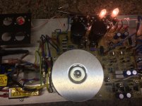

Hello .. this is why I made a power supply test bench, notice the sec fuses before the PSU PCB ... just posted for info
Right...need to think about where these would go in the actual case....your test rig has an extra bit of room!! 🙂
Can you please point me towards the fuse holder that you are using....and also recommend values for Primary and/or 2ndary fuses...?
OK...all 4 Rectifier Diodes (BYX49) removed/tested/replaced...good.
Reservoir caps removed (4700mfd 80v X 2)
Visually...one of them showed signs of leaking of black substance from around 'white' terminal...this was hard/dry. Some slight bowing of the connector plate.
This one has continuity between White/Case
"2nd Cap....no leaking/bowing....but shows continuity between Red/Case and White/Case
....is it fair to say that they're stuffed?? 🙂
If you have capacity meter, or some dmm can measure , check if capacity is ok. Ofcourse if capacitors don't shorted.
- Home
- Amplifiers
- Solid State
- Hart JLH find....please help with identity/info!!