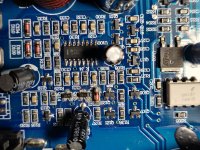
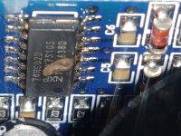
Got a Hardbass 2000.1 monoblock here that is not powering up. A repair was attempted on it prior to my getting it and not sure what is right and wrong. I do know that the TL494 is not getting high enough voltage but some SMD transistors and a zener diode look like they have been replaced. I will post the TL494 voltages:
1)4.33
2)3.23
3)3.61
4)0.0
5)1.19
6)2.95
7)0.0
8)5.41
9)0.0
10)0.0
11)5.41
12)5.41
13)4.33
14)4.33
15)1.46
16)0.13
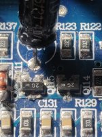
Q111 zener diode looks replaced. There is 5.96v and 5.41v on each end. When removed there is 13v on the end with 5.96v and the 5.41v is still on the pad for the other end.
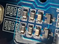
Q114 and Q115 have been replaced with MMBTA56. Not sure if those should be in there.
Any help would be greatly appreciated. Thanks.
1)4.33
2)3.23
3)3.61
4)0.0
5)1.19
6)2.95
7)0.0
8)5.41
9)0.0
10)0.0
11)5.41
12)5.41
13)4.33
14)4.33
15)1.46
16)0.13
Q111 zener diode looks replaced. There is 5.96v and 5.41v on each end. When removed there is 13v on the end with 5.96v and the 5.41v is still on the pad for the other end.
Q114 and Q115 have been replaced with MMBTA56. Not sure if those should be in there.
Any help would be greatly appreciated. Thanks.
Attachments

http://www.bcae1.com/temp/SLA1500.pdf
On page 2 of the diagram above you can see Q17 and Q18. Find the corresponding transistors in your amp.
On page 2 of the diagram above you can see Q17 and Q18. Find the corresponding transistors in your amp.
Q114 and Q115 correspond to Q17 and Q18 in the SLA1500 schematic. Those locations have MMBTA56 in them.
Post the DC voltage on all 3 terminals of those transistors.
Q114
base:
collector:
emitter:
Q115
base:
collector:
emitter:
Q114
base:
collector:
emitter:
Q115
base:
collector:
emitter:
Q114
base:5.51
collector:5.41
emitter:13.6
Q115
base:5.51
collector:5.41
emitter:13.6
Those are without remote applied. With remote applied the base of Q114 remains at 5.41 while the base of Q115 goes to 0v.
base:5.51
collector:5.41
emitter:13.6
Q115
base:5.51
collector:5.41
emitter:13.6
Those are without remote applied. With remote applied the base of Q114 remains at 5.41 while the base of Q115 goes to 0v.
I replaced Q114 and now there is 0v on the base of them. There is still 5.41v on their collectors. The collectors are directly connected to Pin8 and Pin12 of the TL494 along with R120, R121 and C120.
Replaced Q115 as well and the amp powered up. Using the speaker - terminal as ground the rails are ±50v but I am reading -50v across the speaker terminals.
Also, the green power LED is not illuminated. The non grounded lead of the LED reads +13.1v. Is this the correct voltage for a power LED or is the driver circuit defective?
Also, the green power LED is not illuminated. The non grounded lead of the LED reads +13.1v. Is this the correct voltage for a power LED or is the driver circuit defective?
I will check the outputs tomorrow and post the findings. I don't remember any being shorted but this currently has IRFB31N20D in it while the originals were IRFB23N15D. Definitely have output or driver board issues to rectify. Glad it is powering up though.
Should the LED + be +13v?
Should the LED + be +13v?
Yes, I have scopes. I have a DSO and a OWON VDS1022I, however I am currently renovating so the OWON is a hassle right now since the computer is difficult to access.
The outputs are not shorted as they test ok when removed and new replacements do the same thing when installed. What is happening is that when powered up, Q207 and Q208 read shorted between Drain and Source.
Unfortunately, this multimeter (Sinometer VC9808+) does not read transistors the same as my now malfunctioning Mestek DM91A when on continuity/diode check. With the Sinometer on diode check, black probe on Drain and red probe on Source or Gate, the meter beeps and show 0. Probes reversed it reads OL. Q209 and Q210 do not read anything at all when these checks are performed. Don't know if I have driver board issues or diode issues, etc.
Attachments

- Home
- General Interest
- Car Audio
- Hardbass mono not turning on