DIYaudio Members:
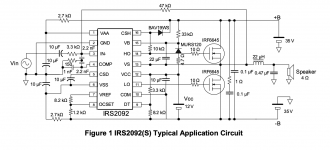
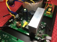
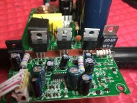
My friend asked me to look at his Harbinger Powered Speaker. It uses a mono Class D amp with the IRS2092S amp module. Currently, there is no output. I am hoping Harbinger will send me a schematic. The output seems to be going to a Second Order Crossover that is on the Power Amp / Power Supply Board. I am looking at generic schematics for the IRS2092S but there seem to be differences.
The Low Speaker output has 40 volts dc on it. So there is an issue. The two Mosfets tested good. The board also uses a TIP41C NPN transistor - also tested good.
The Power Supply is your traditional Transformer, Bridge Rectifier, two caps. The plus and minus 50 volts are working. I am not a Class D expert but it seems rare that this Class D amp is not using a SMPS.
Any ideas on troubleshooting or trying to find a schematic that might be close to this particular unit?
Thanks in advance, Tom
Hi Jon...
I reinserted the Mosfets and TIP41C. For now, I left the heatsink unattached. On both the High and Low outputs, I see a sine wave of 440Khz at 7vrms. I no longer measure any DC at the output. I am tempted to run a small signal through the amp.
Tom
I reinserted the Mosfets and TIP41C. For now, I left the heatsink unattached. On both the High and Low outputs, I see a sine wave of 440Khz at 7vrms. I no longer measure any DC at the output. I am tempted to run a small signal through the amp.
Tom
My experience of 2092 amps is when they fail its often mosfets which take with them the 2092. Never replace one without the other.
Well... it appears I can now pass a signal. I will test the amp over the next few days to make sure it continues to work. When I look at Pin 14 (High Out) on the chip, I see a nice square wave , 700mv. But Pin 11 (Low Out) has a weirdo looking square wave and only 93mv. Maybe it is supposed to be that way? I am not familiar with how this IC works. Anyway... I will follow up in a couple days. Thanks again Jon and Nigel.
Attachments
Epilog:
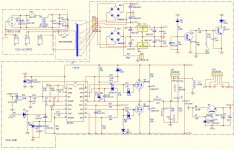
For those interested, here is a copy of the schematic for the Power Supply and Amp. It's interesting to see how they modified the typical IRS2092S application to fit their needs. I can now see how they created to Low and High outputs.
Thanks to our friends at Harbinger for sending this to me.
Tom
For those interested, here is a copy of the schematic for the Power Supply and Amp. It's interesting to see how they modified the typical IRS2092S application to fit their needs. I can now see how they created to Low and High outputs.
Thanks to our friends at Harbinger for sending this to me.
Tom
Attachments
Hi TomCarlos,
I have on my bench a 2115 with the same problem - DC across the "low" speaker output. Thanks for posting the schematic, it's an immense help.
I know it's an old thread, but hopefully you still remember the details.
I was just wondering what ended up being the fix - based on your description it sounds like you just took the MOSFETs and complementary power transistor out, reinserted them, and that was all. Is that accurate? If so, do you think it was simply a solder joint issue? I can't quite see how that could create this problem.
No problem if you can't recall, again thanks for posting the schematic.
Hey AshlandSoundMachines,
Did you ever find out why you had DC across the the speaker out ? I have the same issue, I replaced a few components mosfets, resistors, diodes and the IRS2092. Thought everything was golden because I had a sine wave and nothing was putting out magic smoke anymore. I put with a dummy load 8ohm resistor on and it was heating up fast. Metered and saw I have rail voltage on the outputs -53V.
Anyway i'm at a loss here, maybe someone can point me in the right direction.
I would remove dummy load and check for oscillation of the amp.
You need to check for DC on output before connecting a load.
You need to check for DC on output before connecting a load.
With the dummy load removed this is what I have across the LF Speaker out without the two mosfets on. Forgive me as i'm just starting with amp repair and don't have the best tools or much of a working knowledge yet

Last edited:
Check the gate voltages on the MOSFET's.
Only attach/disconnect scope probes when amp is off.
Sounds like positive rail mosfet isnt turning on.
Only attach/disconnect scope probes when amp is off.
Sounds like positive rail mosfet isnt turning on.
The top mosfet gate should go to positive rail.
The bottom mosfet gate should go to about 12 volts above negative rail.
The bottom mosfet gate should go to about 12 volts above negative rail.
Without any output MOSFETs you can check lo-side gate drive. Hi-Side gate drive won't work at all because it requires the lo-side power MOSFET to enable the charge pump. If you re-connect the lo-side MOSFET only, you can check bot gate drives without any danger of ka-boom
Hey, sorry I should have mentioned I put both Mosfets back on before scoping the gate. The top picture is pin 1 Q4 bottom picture is pin 1 Q5. Still negative 22v DC on the Low out.
Looks like both gates have negative DC voltage??
Q4 pin 1 -30VDC
Q5 pin 1 -55VDC
Looks like both gates have negative DC voltage??
Q4 pin 1 -30VDC
Q5 pin 1 -55VDC
Last edited:
They should both start from negative.
Bottom mosfet gate goes from neg rail to about 12 volts above neg rail when high.
Top mosfet should go from neg rail up to around pos rail when high.
Bottom mosfet gate goes from neg rail to about 12 volts above neg rail when high.
Top mosfet should go from neg rail up to around pos rail when high.
A class d amp oscillates so a signal is there all the time to the mosfets.
A typical frequency would be about 200KHz .
On the output before the LC filter will be a rail to rail square wave.
A typical frequency would be about 200KHz .
On the output before the LC filter will be a rail to rail square wave.
- Home
- Amplifiers
- Class D
- Harbinger Class D Amp with Crossover - No Output