I got this power amp and I would like to convert it for guitar use. I plan to dump the 6J5 tubes and use the sockets for a preamp and PI instead. I haven't been able to find any useable schematics for a 4x 6V6 PPP design. I have some 6SN7 and 6SJ7s I can use. Any thoughts on what I can do with what I have here?
Attachments
If it's in working condition, with tubes, etc., I'd use it basically as what it is, a *good* power amp, with the only mod of turning those 6J5 into an LTP inverter , or this one which leaves everything as is, needs only an extra resistor:
And then would mount the Hammond G in the bottom of the cabinet, and build a new, modern preamp (modern means from 1955 up") ) on a subchassis on top (similar to split chassis Gibson/Magnatone/etc.), fed through an umbilical which carries power up and signal down.
) on a subchassis on top (similar to split chassis Gibson/Magnatone/etc.), fed through an umbilical which carries power up and signal down.
Best of both worlds: you mount the clunky heavy hot Power amp + PSU below, and a nice preamp upstairs.
Even a single 12AX7 will give you a classic Blackface preamp.
A killer combination with those 6V6 .
Plus there's no practical way to mount a preamp, specially preamp controls, jacks, etc. in that chassis.
You are comitted to get a neew chassis anyway, simplest is to worry only about a light practical preamp.
Good luck.
An externally hosted image should be here but it was not working when we last tested it.
And then would mount the Hammond G in the bottom of the cabinet, and build a new, modern preamp (modern means from 1955 up
) on a subchassis on top (similar to split chassis Gibson/Magnatone/etc.), fed through an umbilical which carries power up and signal down.Best of both worlds: you mount the clunky heavy hot Power amp + PSU below, and a nice preamp upstairs.
Even a single 12AX7 will give you a classic Blackface preamp.
A killer combination with those 6V6 .
Plus there's no practical way to mount a preamp, specially preamp controls, jacks, etc. in that chassis.
You are comitted to get a neew chassis anyway, simplest is to worry only about a light practical preamp.
Good luck.
True enough.
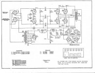
I sort of expected something like this because the power amp has 2 inputs, presumably already out of phase, and straight to the grids, which didn't even had ground return resistors (they trust the driver transformer in the preamp chassis).
The preamp is very interesting and certainly most advanced, but I see it *too* Hammond organ especific, maybe you'd have to strip at least part of it, but leaving V5 which is the phase inverter.
It has what must have been the best tremolo in the World, but it's too complex and parts of it seem to be "somewhere else", probably at some control panel by the organ keyboard.
*Maybe* your best bet is to (slightly) mod the power amp so it can work on its own and it can accept "any" guitar preamp you build.
And use the preamp as a "donor chassis".
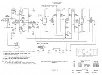
Just to know where you're standing, do the next:
1) ground the NET C10/R24/R25 to put that triode out of the scene.
2) lift "in the air" the left leg of C11.
"left" means "as seen on schematic" meaning "the one that's connected to R21".
On the actual chassis it may be pointing *anywhere*, what matters is what it's connected to.
Now that's your input.
Mount a jack in the chassis, ground to ground, hot to C11 .
Plug a guitar, use its volume and tone controls because you have none in the chassis, play.
What do you hear?
Do you find it acceptable?
Note: a NET is "some part leg and everything that's connected to it" , so all points "are the same" meaning all have same voltage, signal, whatever, and if you ground any point of that NET, all of it gets grounded.
Of course, "ground" is the largest net of them all and is everywhere.
Speaking "Nets" is actually the simplest way of making connections clear, and it's not necessary to mention all of it, usually naming 2 parts of it is enough to identify it; for example I didn't mention R18 but it's clear that one of its legs is also part of the NET mentioned earlier.
Just to know where you're standing, do the next:
1) ground the NET C10/R24/R25 to put that triode out of the scene.
2) lift "in the air" the left leg of C11.
"left" means "as seen on schematic" meaning "the one that's connected to R21".
On the actual chassis it may be pointing *anywhere*, what matters is what it's connected to.
Now that's your input.
Mount a jack in the chassis, ground to ground, hot to C11 .
Plug a guitar, use its volume and tone controls because you have none in the chassis, play.
What do you hear?
Do you find it acceptable?
Note: a NET is "some part leg and everything that's connected to it" , so all points "are the same" meaning all have same voltage, signal, whatever, and if you ground any point of that NET, all of it gets grounded.
Of course, "ground" is the largest net of them all and is everywhere.
Speaking "Nets" is actually the simplest way of making connections clear, and it's not necessary to mention all of it, usually naming 2 parts of it is enough to identify it; for example I didn't mention R18 but it's clear that one of its legs is also part of the NET mentioned earlier.
Tried this and output was very low, I will need much more gain than that.
Ok, testing beats everything else.
Consider that point your Power Amp Input .
Feel free to pull everything to its left and build whatever you want.
That preamp will have its own filament transformer but receives +V from the main chassis.
I think a 5E3 preamp or an earlier, octal tube version, is a good choice, specially because front panel controls will be simple , yet good sounding.
3 pots, 4 jacks, killer sound
Not sure what you are warning, though I agree the speakers need to be dealt with.
The voice coils are typical 8 ohm voice coils, and the amp has no idea what sort of magnets are on them.
But the power supply does expect to see the field coils - and the resistances are given. Without that 5k resistance from B+ to ground, the voltages will be way off, and the smaller one rides on the underside of the filter caps.
I used to rebuild old juke box amps, and enough of them had field coils that I still have a large 50w 5k resistor with clip leads for the purpose of substitution for the fielde coils while the amp was benched. That was the fix for replacing the FC speaker with a permanent magnet type, we added a power resistor in the chassis.
The voice coil 10W, but the field coil...20W at least.
Sorry, the words 'field coil' were lost somewhere in the ether...I meant to say that the power supply expects to see a field coil load, and often the field coil was doubled as an additional choke. When adding a resistor to load the field coil supply one should be careful about wattage choice and mounting style - it will get very hot.
Not sure what you are warning, though I agree the speakers need to be dealt with.
Sorry, the words 'field coil' were lost somewhere in the ether...I meant to say that the power supply expects to see a field coil load, and often the field coil was doubled as an additional choke. When adding a resistor to load the field coil supply one should be careful about wattage choice and mounting style - it will get very hot.
The Hammond preamp is very strange, it looks to me like the 6SN7s are used as a PP output not a phase inverter. The signal is inverted in the previous stage. So now I think Ill keep the power amp circuit as is. Gut most of the preamp leaving V5 and the output/interstage transformer and use the left over tubes/socket as a preamp an PI for V5. Any obvious faults in this plan of action?
Fine.
In post #9 I suggested you consider that point where you injected your guitar the "original power amp input", although it physically lives in the "preamp" and feel free to do whatever you please whith what's "to the left of it", in the Preamp drawing, of course.
Would be the most practical combination: keep that killer Hammond power amp and add a "Guitar" type preamp.
One of the old Tweed Fender types, with 2 "channels" (4 inputs) "bright" and "normal" , 2 volume controls, 1 single tone, will probably be a *loud* mean killer Blues machine.
You want Metal?
Add some pedal or Pod in front.
Injecting into the original input gave me a very weak and distorted output, almost no gain at all. The input signal from the organ was way higher than a guitar. Would I need to make any changes to the power amp or can I leave it as is and use it with say a fender 5E3 pre and PI? Maybe a MV between them? And yes, a *loud* mean killer Blues machine is just what Im after.
Oh, that's (bad) news.
I understood you got low volume but good sound, sorry.
I wanted to keep it as simple as possible, and having an already working power amp meant saving a lot of workm but if it's not so, my personal decision (others may differ, of course) would be rather that endlessly chase our tails, strip it and straight build something tried and true.
A full 5E3 comes to mind, since you like it, with only 2 mods:
1) getting a "4x6V6" schematic is easy, just take a "2x6V6" one and double the number of tubes.
You already have the iron
2) to simplify things, I'd go for a cathode biased power amp.
Of course you'll need to halve the cathode resistor and double its power rating.
3) one doubt is about what actual power voltage you will have, since the original PSU is unconventional (and that's an understatement).
a) the transformer shows 2 x 430VAC windings ... yet it shows only 300 VDC +B
Well, it's a choke input PSU so DC voltage is close to *average* voltage, not peak .
Anyway that should give us around 400V +B .... how come it shows only 300?
b) fact is, it's wired as sort of a split supply, those tubes *are* cathode biased after all.
the cathode resistors are the 250 ohms fielld coils, which drop about 55V, so actual +B is around 360V.
See that the filter cap (C5/C6/C7) negatives are *not* grounded but "floating".
They are wasting 55V just to feed those electromagnet coils.
I would use "normal" (permanent magnet) speakers, wire a conventional (still choke input) PSU to get good 400V to ground, disconnect those cathode feedback taps at the output transformer and build a 5E3 type preamp and PI in those 2 octal sockets.
What do you think about that?
Just to feed my curiosity, please measure what voltage you have across the main filter caps, and across field coils.
And if you want to still use those field speakers, I'd build a small, extra 55V to 60V auxiliary PSU and stick it somewhere, just for the field coils.
That amplifier certainly was designed and built with the best of the best, spending whatever was necessary.
Kudos to Mr Hammond !!!!!
.
I understood you got low volume but good sound, sorry.
I wanted to keep it as simple as possible, and having an already working power amp meant saving a lot of workm but if it's not so, my personal decision (others may differ, of course) would be rather that endlessly chase our tails, strip it and straight build something tried and true.
A full 5E3 comes to mind, since you like it, with only 2 mods:
1) getting a "4x6V6" schematic is easy, just take a "2x6V6" one and double the number of tubes.
You already have the iron
2) to simplify things, I'd go for a cathode biased power amp.
Of course you'll need to halve the cathode resistor and double its power rating.
3) one doubt is about what actual power voltage you will have, since the original PSU is unconventional (and that's an understatement).
a) the transformer shows 2 x 430VAC windings
... yet it shows only 300 VDC +BWell, it's a choke input PSU so DC voltage is close to *average* voltage, not peak .
Anyway that should give us around 400V +B .... how come it shows only 300?
b) fact is, it's wired as sort of a split supply, those tubes *are* cathode biased after all.
the cathode resistors are the 250 ohms fielld coils, which drop about 55V, so actual +B is around 360V.
See that the filter cap (C5/C6/C7) negatives are *not* grounded but "floating".
They are wasting 55V just to feed those electromagnet coils.
I would use "normal" (permanent magnet) speakers, wire a conventional (still choke input) PSU to get good 400V to ground, disconnect those cathode feedback taps at the output transformer and build a 5E3 type preamp and PI in those 2 octal sockets.
What do you think about that?
Just to feed my curiosity, please measure what voltage you have across the main filter caps, and across field coils.
And if you want to still use those field speakers, I'd build a small, extra 55V to 60V auxiliary PSU and stick it somewhere, just for the field coils.
That amplifier certainly was designed and built with the best of the best, spending whatever was necessary.
Kudos to Mr Hammond !!!!!
.
I was kinda hoping I could leave the power amp as it is and build a separate preamp as I have piles of old organ amps to work with already. I have not checked voltages, Im waiting until I replace the filter caps before powering it up again. I do plan on replacing the field coils as well which if done right should bring the B+ up a bit. Cathode bias is also a good idea since it sort of already is. Would cathode bias require well matched tubes since they would share a bias reistor? Half the tubes have been replaced over the years. This thing dates to 1946.
- Status
- This old topic is closed. If you want to reopen this topic, contact a moderator using the "Report Post" button.
- Home
- Live Sound
- Instruments and Amps
- Hammond Type G Amp