Russ White said:Ultra simplified folded cascode I/V 🙂 Just to show I have not been lazy. 😉
Hi Russ
Have you read these threads? 😉
http://www.diyaudio.com/forums/showthread.php?s=&threadid=6121&perpage=25&highlight=&pagenumber=1
http://www.diyaudio.com/forums/showthread.php?s=&threadid=54608
I hate this...
This thread is really going somewhere, but all the interesting discussions take place while I'm asleep! No matter what I try, I'll always be late with my replies. Quite hard to participate in this way.
The folded cascode you drew up looks like the concept to aim for. If you add the current mirroring of the original schematic to Q2, then you'll have something that is very hard to beat!
Russ White said:Ok I figured it out how to lower the input Z. Or rather the relationship between the current through CFP and the input Z. 🙂
The more current through QA1.1/QA1.2 the lower the Z.
with 1K at R3/R4 the input Z is around 250mohm while changing those to 100ohm make the input Z 70mohm.
The trade off is slightly worse THD the lower R3/R4.
The higher THD is because the transistors are less linear at the increased current. Otherwise you are pretty much spot on; higher current means a lower input impedance.
Russ White said:Hi WMS,
It seems there is nothing new under the sun. 🙂
As to the DC input point.
I have taken measurements of the Buffalo into the IVY(THS4131 configured for I/V) and it seems to settle at 760mv. So that makes me wonder, if the point should be 0V or 1.65V or .76V. 😕
Or if the IV stage should be set to 0V with no input and allowed to drift naturally with the current applied from the DAC.
I really don't know what is best.
Cheers!
Russ
IVY's 760mV is due to input resistors. Since Sabre is a voltage out w/ 195ohm output resistance, I say it should be referenced to 0V (you will get a little less than 9mA of bias current). Sabre output is really quite good and can handle output input impedance w/o problems (there is a little THD loss due to internal resistors' temperature coefficient).
But I might be wrong 😉
Cheers,
Matej
I've forgot to mention one thing: 100mOhm or 200mOhm would not make any sound difference (at to Sabre), more important is that it is constant no matter what output amplitude is.
Cheers,
Matej
Cheers,
Matej
Yes, well 4 channels in parallel gives (781/4)=195 ohm.
Russ has explained this here really nicely (I couldn't have written it better):
http://www.diyaudio.com/forums/showthread.php?postid=1441029#post1441029
- Matej
Russ has explained this here really nicely (I couldn't have written it better):
http://www.diyaudio.com/forums/showthread.php?postid=1441029#post1441029
- Matej
matejS said:
IVY's 760mV is due to input resistors.
But I might be wrong 😉
Cheers,
Matej
I was talking about the IVY configured for true I/V. No resistor on input, just a jumper. 🙂
Cheers!
Russ
matejS said:
IVY's 760mV is due to input resistors. Since Sabre is a voltage out w/ 195ohm output resistance, I say it should be referenced to 0V (you will get a little less than 9mA of bias current). Sabre output is really quite good and can handle output input impedance w/o problems (there is a little THD loss due to internal resistors' temperature coefficient).
But I might be wrong 😉
Cheers,
Matej
Unfortunately, I believe on both accounts.
WRT offset, ref my post above and ref to THS41xx data sheet.
WRT voltage OP THD, it is more the active devices used for switching
the unity weighted OP bits rather than the resistors themselves.
cheers,
Terry
No for something I hope you'll really like...
🙂
I will let the PDF do the talking.
Well ok a few hints...
No DC offset at the outputs, and no output caps.
Cascodes all over, including a couple folded ones.
Input impedance is about 80mOhm.
Only one resistor to set output voltage.
Only one cap for the bulk of filtering.
But this is no longer a Haiku. It deserves a name of its own.
I am leaning toward "Counterpoint".
Please keep in mind. The attached schematic is neither finished nor tested. Just simulated. But it only needs a few tweaks I think.
Cheers!
Russ
Attachments
I like
Looks like you've caught cascode fever, which is a good thing. Fortunately, small signal silicon is relatively cheap.
But don't stop there...do consider also cascoding Q24, Q23, Q9/29, Q30/30, Q12, Q4. Fortunately...
Even if you decide these ones to be unnesc, do consider leaving pads/holes for mods to add them.
Possibly consider a large cap at the OCM node to have the offset track the average of the signal, rather than the actual signal. Offset loops are usually happier that way.
And, look at the corner frequency of the input impedance, wherever it occurs, 1k, 10k, wherever. Consider adding a cap (single cap hooked up differential) at the input to match somewhere around that knee. Adjust to keep the loop stable. This may seems counterintuitive, as in it would appear to increase noise gain of the loop. However, when tuned, it would further cut down out band noise.
Share and enjoy,
WMS
Hi WMS. 🙂 Yes I had thought about cascoding those Qs too, but was not sure how many Qs I really wanted to add. 🙂
As for the servo bit, I was actually hoping that by actually tracking the signal I might gain some linearity and that each end could then actually be used signal ended with lower distortion simulation bears this out. The two Cs at the summing point keep that bit stable.
I will look into the filtering bit.
Cheers!
Russ
One other note the way I drew the schematic makes it seem that the two halves are inverting. They are not. 🙂 It was just a typo when designating OUT+ and OUT-.
Cheers!
Russ
Cheers!
Russ
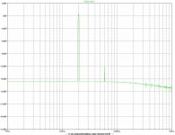
Simulation results. (I know, its just a sim)
Here is the FFT at 20khz 0db input for buffalo 2VRMS output 10K load.
-128db THD.
Here is the FFT at 20khz 0db input for buffalo 2VRMS output 10K load.
-128db THD.
Code:
Fourier components of V(out+,out-)
DC component:2.20805e-010

Harmonic	Frequency	 Fourier 	Normalized	 Phase  	Normalized
 Number 	  [Hz]   	Component	 Component	[degree]	Phase [deg]
    1   	2.000e+04	2.799e+00	1.000e+00	   -6.90°	    0.00°
    2   	4.000e+04	3.181e-10	1.136e-10	  -71.26°	  -64.35°
    3   	6.000e+04	1.102e-06	3.936e-07	    4.42°	   11.32°
    4   	8.000e+04	6.027e-10	2.153e-10	  -70.32°	  -63.42°
    5   	1.000e+05	6.899e-09	2.465e-09	  166.18°	  173.08°
    6   	1.200e+05	1.030e-09	3.680e-10	  110.83°	  117.73°
    7   	1.400e+05	5.653e-09	2.020e-09	   -8.89°	   -1.99°
    8   	1.600e+05	6.990e-10	2.497e-10	  -77.65°	  -70.74°
    9   	1.800e+05	1.046e-08	3.736e-09	  130.35°	  137.25°
Total Harmonic Distortion: 0.000039%
Attachments
Thanks freak.
I will probably lay this out pretty soon, along with the Haiku too (actually already done the Haiku). As I think both will sound great.
Whats interesting about this "counterpoint" circuit, is I basically took my own discrete fully differential opamp, removed the feedback and the output stage, added some current, and a resistor and filter caps, took the input at the emitters of the input pair instead of the bases, then some tweaking, and there you have it....
CMRR and PSRR should both be excellent.
Cheers!
Russ
Re: No for something I hope you'll really like...
Russ,
Well you have done a pretty damn good job.
I was interested to see how you were going to get the (folded)
cascode linear, as this is where the linearity usually gets spoiled.
As you probably found out, you need the CFP in the folded cascode
part to get linearity similar to the non folded design.
I don't quite get the dc offset arrangement, I'm thinking Vocm
actually needs to come from a common mode sum of both outputs,
presumably LP filtered.
As such it becomes a type of CM servo comparing OP with ground,
yes?
I have been doing many folded cascode designs myself, somewhat
different to yours. They go from simple to pretty complex.
So far my best result, which is a fairly complex CCT simulates at
< 0.000002% (-156dB) between phases (balanced OP) and
~ 0.000005% (-146dB) at each phase OP THD.
That is with Sabres 195 R / 8mA at IP and 2V RMS OP per phase.
Admittedly at these low levels it's just a numbers game but it
was an interesting challenge to progressively identify and eliminate
/ reduce all the non linearities.
Also probably at these levels of simulated distortion, I think other
things will be more audible. As WMS has stated, probably thermal
junction effects will be one of them.
Also, when you implement the double CFP folded arrangement,
don't be surprised if you get oscillation problems. CFP's really love
to oscillate when done on real world pcbs. If such is the case,
base stoppers, usually a hundred ohms or so can settle things.
The only other thing I wanted to mention about your design is that
it looks to have a pretty high noise gain from the various CCS's
to OP R. This means that all the various CCS BJT's voltage noise will
be multiplied by the ratio of load R to CCS R.
This can be rectified by using lower noise BJT's in CCS's and
increasing the ref voltage and R value.
Also, just thinking about it the CCT appears to have very high CM
OP impedance, since load R is floating between phases.
This may have some large noise implications, depends on how the
CM servo is implemented.
Cheers
Terry
Russ White said:🙂
I will let the PDF do the talking.
Well ok a few hints...
No DC offset at the outputs, and no output caps.
Cascodes all over, including a couple folded ones.
Input impedance is about 80mOhm.
Only one resistor to set output voltage.
Only one cap for the bulk of filtering.
But this is no longer a Haiku. It deserves a name of its own.
I am leaning toward "Counterpoint".
Please keep in mind. The attached schematic is neither finished nor tested. Just simulated. But it only needs a few tweaks I think.
Cheers!
Russ
Russ White said:Simulation results. (I know, its just a sim)
Here is the FFT at 20khz 0db input for buffalo 2VRMS output 10K load.
-128db THD.
Code:Fourier components of V(out+,out-) DC component:2.20805e-010 Harmonic Frequency Fourier Normalized Phase Normalized Number [Hz] Component Component [degree] Phase [deg] 1 2.000e+04 2.799e+00 1.000e+00 -6.90° 0.00° 2 4.000e+04 3.181e-10 1.136e-10 -71.26° -64.35° 3 6.000e+04 1.102e-06 3.936e-07 4.42° 11.32° 4 8.000e+04 6.027e-10 2.153e-10 -70.32° -63.42° 5 1.000e+05 6.899e-09 2.465e-09 166.18° 173.08° 6 1.200e+05 1.030e-09 3.680e-10 110.83° 117.73° 7 1.400e+05 5.653e-09 2.020e-09 -8.89° -1.99° 8 1.600e+05 6.990e-10 2.497e-10 -77.65° -70.74° 9 1.800e+05 1.046e-08 3.736e-09 130.35° 137.25° Total Harmonic Distortion: 0.000039%
Russ,
Well you have done a pretty damn good job.
I was interested to see how you were going to get the (folded)
cascode linear, as this is where the linearity usually gets spoiled.
As you probably found out, you need the CFP in the folded cascode
part to get linearity similar to the non folded design.
I don't quite get the dc offset arrangement, I'm thinking Vocm
actually needs to come from a common mode sum of both outputs,
presumably LP filtered.
As such it becomes a type of CM servo comparing OP with ground,
yes?
I have been doing many folded cascode designs myself, somewhat
different to yours. They go from simple to pretty complex.
So far my best result, which is a fairly complex CCT simulates at
< 0.000002% (-156dB) between phases (balanced OP) and
~ 0.000005% (-146dB) at each phase OP THD.
That is with Sabres 195 R / 8mA at IP and 2V RMS OP per phase.
Admittedly at these low levels it's just a numbers game but it
was an interesting challenge to progressively identify and eliminate
/ reduce all the non linearities.
Also probably at these levels of simulated distortion, I think other
things will be more audible. As WMS has stated, probably thermal
junction effects will be one of them.
Also, when you implement the double CFP folded arrangement,
don't be surprised if you get oscillation problems. CFP's really love
to oscillate when done on real world pcbs. If such is the case,
base stoppers, usually a hundred ohms or so can settle things.
The only other thing I wanted to mention about your design is that
it looks to have a pretty high noise gain from the various CCS's
to OP R. This means that all the various CCS BJT's voltage noise will
be multiplied by the ratio of load R to CCS R.
This can be rectified by using lower noise BJT's in CCS's and
increasing the ref voltage and R value.
Also, just thinking about it the CCT appears to have very high CM
OP impedance, since load R is floating between phases.
This may have some large noise implications, depends on how the
CM servo is implemented.
Cheers
Terry
Re: Re: No for something I hope you'll really like...
Just saw the OCM network on your schematic 20k//22p, I missed it
hiding down there.
So disregard the statement above about high CM OP impedance,
complete opposite. doh!
For OP noise gain calcs, it appears the effective OP load would be
365R. However, and this is pretty interesting, the CM servo will
force the noise to appear on both outputs differentially.
At a first educated guess, it appears that all the CCS noise
generators need to be multiplied by noise gain, summed
RMS and then will appear fully differentially at both OP's.
Bruno Putzeys would be interested to see this CCT, he is
a bit of a differential circuit wiz.
cheers
T
Terry Demol said:
Also, just thinking about it the CCT appears to have very high CM
OP impedance, since load R is floating between phases.
This may have some large noise implications, depends on how the
CM servo is implemented.
Just saw the OCM network on your schematic 20k//22p, I missed it
hiding down there.
So disregard the statement above about high CM OP impedance,
complete opposite. doh!
For OP noise gain calcs, it appears the effective OP load would be
365R. However, and this is pretty interesting, the CM servo will
force the noise to appear on both outputs differentially.
At a first educated guess, it appears that all the CCS noise
generators need to be multiplied by noise gain, summed
RMS and then will appear fully differentially at both OP's.
Bruno Putzeys would be interested to see this CCT, he is
a bit of a differential circuit wiz.
cheers
T
Hi Terry,
Thanks for good input and kind words.
I can actually did get my cct to simulate next to zero distortion(which is why I think simulation distortion measurements are bollocks, but fun to look at) , but to do that I have to run a lot of current through it and run it right on the edge of stability. Distortion goes up a bit in the cct shown because I added some compensation, but it should be pretty stable I think. If I need to I will add base stoppers, but I am hoping not to have to.
BC550 and BC560 are low noise types, so things should be pretty good to use all the way around the CCT. Any other part suggestions?
Yes my servo is a bit more than an ordinary servo, that is to say its correction bandwidth extends well beyond audio range. 🙂 The very very cool thing I am finding with this cct is that the outputs can easily be taken single ended with just a trivial loss in THD. So people can use this with no BAL/SE conversion. Just double the I/V resistor and halve the filter C and you will get 2VRMS at each phase OP and similar filter response.
Cheers!
Russ
- Status
- Not open for further replies.
- Home
- Source & Line
- Digital Source
- Haiku I/V Stage