I think I am going to go ahead and bag the emiiter followers at the output.
The reason is for any heavy load a person is going to want a buffer anyway. Any load from 10K up should be fine without it.
This way even if I add the cascodes I end up with a reasonable number of parts to try to fit on a Buffalo/COD size board, which is 3.3" x 2".
Cheers!
Russ
The reason is for any heavy load a person is going to want a buffer anyway. Any load from 10K up should be fine without it.
This way even if I add the cascodes I end up with a reasonable number of parts to try to fit on a Buffalo/COD size board, which is 3.3" x 2".
Cheers!
Russ
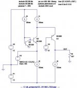
I am also weighing the value of the two cascodes at the input CCS.
I am not sure how much they actually help, in simulation the results are pretty much the same with or without them, even with drastic temperature changes.
I am not sure how much they actually help, in simulation the results are pretty much the same with or without them, even with drastic temperature changes.
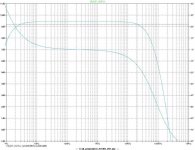
Ok I figured it out how to lower the input Z. Or rather the relationship between the current through CFP and the input Z. 🙂
The more current through QA1.1/QA1.2 the lower the Z.
with 1K at R3/R4 the input Z is around 250mohm while changing those to 100ohm make the input Z 70mohm.
The trade off is slightly worse THD the lower R3/R4.
Cheers!
Russ
The more current through QA1.1/QA1.2 the lower the Z.
with 1K at R3/R4 the input Z is around 250mohm while changing those to 100ohm make the input Z 70mohm.
The trade off is slightly worse THD the lower R3/R4.
Cheers!
Russ
Russ White said:the input Z 70mohm.
The trade off is slightly worse THD the lower R3/R4.
Impressive...I think that's worth it 🙂
fierce_freak said:
Impressive...I think that's worth it 🙂
Well the question is how low to go. 🙂
In simulation it seems 221R at R3/R4 is a sweet spot. The input Z is still < 100 mohm but THD is still right around .000085% at 20khz.
I think that's probably what I will try.
Cheers!
Russ
Ukiah
With a decent topology like this, it's all varying degrees of good.
Lavardin might want a small royalty, even though this implementation is different enough that it probably wouldn't hold up. Their cascode is outside/above the CFB loop, and they use a current source to the positive rail rather than a Vbe set resistor as this (and peufeu's) do. But IANAL just ENGR.
One could argue that the virtual ground input node acts as a cascode for the current source(s), but, if there is space and budget, cascodes ususally sound better to my ears. Cleaner.
Yes, since it will likely be driving 10k and up loads, less than 200 ohms output impedance per leg is fine. Some designs deliberately "damp" emitter followers with 100 to 1k ohms series resistors to ensure stability with all potential reactive loads, so you are ahead of the game leaving them out.
Will you include an option to set the input node DC point, ie 1.6V for Sabre, and gnd/0V for others?
Share and enjoy,
WMS
Hi WMS,
It seems there is nothing new under the sun. 🙂
As to the DC input point.
I have taken measurements of the Buffalo into the IVY(THS4131 configured for I/V) and it seems to settle at 760mv. So that makes me wonder, if the point should be 0V or 1.65V or .76V. 😕
Or if the IV stage should be set to 0V with no input and allowed to drift naturally with the current applied from the DAC.
I really don't know what is best.
Cheers!
Russ
Russ White said:Hi WMS,
It seems there is nothing new under the sun. 🙂
As to the DC input point.
I have taken measurements of the Buffalo into the IVY(THS4131 configured for I/V) and it seems to settle at 760mv. So that makes me wonder, if the point should be 0V or 1.65V or .76V. 😕
Or if the IV stage should be set to 0V with no input and allowed to drift naturally with the current applied from the DAC.
I really don't know what is best.
Cheers!
Russ
Russ,
Are you saying that Vref on Sabre drifts slowly??
cheers
Terry
Terry Demol said:
Russ,
Are you saying that Vref on Sabre drifts slowly??
cheers
Terry
No, not at all, it stays right at 760mv all the time into IVY.
I actually think it may have to do with the way the THS4131 works.
On my prototype Haiku I have the input node close to zero, and it seems to be working fine. So I am not sure why I would want to set it to 1.65V is what I am saying...
On my prototype Haiku I have the input node close to zero, and it seems to be working fine. So I am not sure why I would want to set it to 1.65V is what I am saying...
Russ White said:
No, not at all, it stays right at 760mv all the time into IVY.
Russ
Are you saying if you were to disconnect I-V, then dac OP will sit at
+760mV with 0 signal?
T
Terry Demol said:
Russ
Are you saying if you were to disconnect I-V, then dac OP will sit at
+760mV with 0 signal?
T
Terry, the THS4131 is at 0V with the DAC disconnected. Its at 760mv with it connected. But it stays at 760mv even with 0db (full scale) signal (checking with my PC oscilloscope) so I know the input impedance is indeed close to zero. I don't understand exactly why the 760mv appears. 🙂
Cheers!
Russ
Interestingly, the same exact value appears in simulation with the THS4131 model provided from TI. 🙂 And a similar value in my discrete opamp version which is quite similar.
Now, the Haiku is a very different beast. It only budges a few mv whether the DAC is connected or not. 🙂
Cheers!
Russ
Now, the Haiku is a very different beast. It only budges a few mv whether the DAC is connected or not. 🙂
Cheers!
Russ
Russ White said:
Terry, the THS4131 is at 0V with the DAC disconnected. Its at 760mv with it connected. But it stays at 760mv even with 0db (full scale) signal (checking with my PC oscilloscope) so I know the input impedance is indeed close to zero. I don't understand exactly why the 760mv appears. 🙂
Cheers!
Russ
Russ,
OK I get it now.
Ref fig 29 THS413x data sheet for explanation of relationship of
Vocm to OP offset / IP.
THS413x IP's common mode point is set by the FB resistors,
CM current into IP and will shift to make OP match whatever Vocm is.
So if you set Vocm to 0V, THS413x OP will be at 0V. When Sabre
sources current from THS IP then that current must be equal to
the CM current in the FB resistors on THS. So the IP of THS shifts
high by whatever amount is required for these currents to
be equal.
Clear as mud? 😎
cheers
Terry
Terry Demol said:
Russ,
OK I get it now.
Ref fig 29 THS413x data sheet for explanation of relationship of
Vocm to OP offset / IP.
THS413x IP's common mode point is set by the FB resistors,
CM current into IP and will shift to make OP match whatever Vocm is.
So if you set Vocm to 0V, THS413x OP will be at 0V. When Sabre
sources current from THS IP then that current must be equal to
the CM current in the FB resistors on THS. So the IP of THS shifts
high by whatever amount is required for these currents to
be equal.
Clear as mud? 😎
cheers
Terry
Russ White said:Actually yes, I have been looking it over and it actually does make sense to me now. 🙂
Data sheet seems to indicate 1.65V is optimum for dac OP point
which would be 1.65V for Vocm on THS chip.
It would be interesting to know where Sabre is most linear, but only
Dustin will know that from the internal analog design.
Is he still around here?
cheers
T
Russ White said:I just wonder why it would matter for a current source, as long as the impedance is low....
The answer is probably already looking at us in the data sheet.
With voltage OP Sabre still gets -108dB THD, and that is a dynamically
changing OP state.
Any fixed OP state has to be better WRT linearity of the unity
weighted bit OP architecture.
- Status
- Not open for further replies.
- Home
- Source & Line
- Digital Source
- Haiku I/V Stage