Hi,
Just couldn't resist looking...
Much better! And it has an added bonus too: it will make the DC on the DAC output much less susceptible to power supply variations than the resistive divider you used previously. All in all a superior solution with the equal amount of parts. If you wish to eliminate even more, connect the bases of Q5/6 (in the original schematic) together and use a single bias voltage. That way, the base AC currents cancel out. Of course, this requires Q5/6 to be matched.
The folded cascode is something I'd have to draw in a schematic, and I don't have time for that right now. You already seem to have a workaround for single-ended output, but if you're still interested, please let me know and I'll find some time.
Thanks Timpert,
I will change the circuit to reflect what I have learned. Thanks for the ideas.
I am experimenting with the folded cascode idea. Please share if you draw something up. I would love to see it.
Cheers!
Russ
I will change the circuit to reflect what I have learned. Thanks for the ideas.
I am experimenting with the folded cascode idea. Please share if you draw something up. I would love to see it.
Cheers!
Russ
Hello Russ!
About discrete oprational amplifiers...I had good experiences with the stuff Erno Borbely makes..what do You think of his designs.?
Do want to achieve the same level or beyond with fewer and cheaper parts?
regards
Georg
About discrete oprational amplifiers...I had good experiences with the stuff Erno Borbely makes..what do You think of his designs.?
Do want to achieve the same level or beyond with fewer and cheaper parts?
regards
Georg
lfat said:Hello Russ!
About discrete oprational amplifiers...I had good experiences with the stuff Erno Borbely makes..what do You think of his designs.?
Do want to achieve the same level or beyond with fewer and cheaper parts?
regards
Georg
I have a fully differential (super symmetrical) discrete op amp in the works, and it works very very well, but this particular design is for those who want to try something with no global feedback.
You can read about that design here:
http://www.diyaudio.com/forums/showthread.php?postid=1444986#post1444986
Cheers!
Russ
OK one option would be to use a THAT300 device and parallel two of the Qs to get the base reference voltage for Q5 and Q6. The should give us ideal thermal tracking/coupling and excellent device matching.
I am guessing I would want to put a small resister at the emitters of the ref Qs to make them share current equally.
What do you guys think?
Something like this, and please forgive the roughness of the simulation I did it quickly:
Cheers!
Russ
I am guessing I would want to put a small resister at the emitters of the ref Qs to make them share current equally.
What do you guys think?
Something like this, and please forgive the roughness of the simulation I did it quickly:
Cheers!
Russ
Attachments
Haiku Rev 2 🙂
OK, here is a proper schematic with the THAT300 devices and only one TL431. 🙂 Don't need the big caps at the VREF anymore.
I don't have any of the THAT300s handy to test right now, so I just am using BC550s. But it works fine! 🙂
Here is revision 2:
Cheers!
Russ
OK, here is a proper schematic with the THAT300 devices and only one TL431. 🙂 Don't need the big caps at the VREF anymore.
I don't have any of the THAT300s handy to test right now, so I just am using BC550s. But it works fine! 🙂
Here is revision 2:
Cheers!
Russ
Attachments
Re: Haiku Rev 2 🙂
Hi Russ
2 questions,
- How does it measure (simulated)?
- How does it sound compared to the OPA version?
You previously mentioned a lot of OOB noise from this dac,
so the non GFB design may be an advantage in this regard.
cheers
Terry
Russ White said:OK, here is a proper schematic with the THAT300 devices and only one TL431. 🙂 Don't need the big caps at the VREF anymore.
I don't have any of the THAT300s handy to test right now, so I just am using BC550s. But it works fine! 🙂
Here is revision 2:
Cheers!
Russ
Hi Russ
2 questions,
- How does it measure (simulated)?
- How does it sound compared to the OPA version?
You previously mentioned a lot of OOB noise from this dac,
so the non GFB design may be an advantage in this regard.
cheers
Terry
Hi Terry,
Well I have only heard one mono channel. 🙂 So I can only say it seems to sound fine. Absolutely no noise or hiss. I will have to leave the heavy duty listening until I can make up another channel.
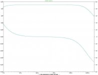
This is what the simulation says for 20khz into 47K load 2VRMs differential.
Well I have only heard one mono channel. 🙂 So I can only say it seems to sound fine. Absolutely no noise or hiss. I will have to leave the heavy duty listening until I can make up another channel.
This is what the simulation says for 20khz into 47K load 2VRMs differential.
Code:
Harmonic	Frequency	 Fourier 	Normalized	 Phase  	Normalized
 Number 	  [Hz]   	Component	 Component	[degree]	Phase [deg]
    1   	2.000e+04	2.968e+00	1.000e+00	  179.99°	    0.00°
    2   	4.000e+04	3.328e-09	1.121e-09	  158.19°	  -21.79°
    3   	6.000e+04	1.558e-06	5.250e-07	 -144.69°	 -324.68°
    4   	8.000e+04	1.296e-09	4.366e-10	  -77.55°	 -257.54°
    5   	1.000e+05	1.627e-08	5.483e-09	   39.11°	 -140.88°
    6   	1.200e+05	2.221e-09	7.484e-10	   83.65°	  -96.34°
    7   	1.400e+05	5.012e-09	1.689e-09	  170.24°	   -9.75°
    8   	1.600e+05	6.735e-10	2.269e-10	 -168.03°	 -348.02°
    9   	1.800e+05	9.354e-10	3.152e-10	 -113.09°	 -293.07°
Total Harmonic Distortion: 0.000053%
Russ White said:Hi Terry,
Well I have only heard one mono channel. 🙂 So I can only say it seems to sound fine. Absolutely no noise or hiss. I will have to leave the heavy duty listening until I can make up another channel.
This is what the simulation says for 20khz into 47K load 2VRMs differential.
Code:Harmonic Frequency Fourier Normalized Phase Normalized Number [Hz] Component Component [degree] Phase [deg] 1 2.000e+04 2.968e+00 1.000e+00 179.99° 0.00° 2 4.000e+04 3.328e-09 1.121e-09 158.19° -21.79° 3 6.000e+04 1.558e-06 5.250e-07 -144.69° -324.68° 4 8.000e+04 1.296e-09 4.366e-10 -77.55° -257.54° 5 1.000e+05 1.627e-08 5.483e-09 39.11° -140.88° 6 1.200e+05 2.221e-09 7.484e-10 83.65° -96.34° 7 1.400e+05 5.012e-09 1.689e-09 170.24° -9.75° 8 1.600e+05 6.735e-10 2.269e-10 -168.03° -348.02° 9 1.800e+05 9.354e-10 3.152e-10 -113.09° -293.07° Total Harmonic Distortion: 0.000053%
Good results and predictably H3 dominant.
If you look at each phase, the H2 will be around 10 x the residual
H3 of the balanced OP measurements as shown... it's like cheating
a bit 🙂
The almost zero PSRR of each phase means good PS is
required and will be pretty audible.
WRT noise, generators will be CCS's, a different scenario to the
typical opamp arrangement noise wise.
Nice design.
cheers
Terry
fierce_freak said:Nice, Russ!
Terry Demol said:Nice design.
cheers
Terry
Thanks Guys! 🙂
Lets see how the real thing does.
I am still open to looking at a folded cascode solution.
Cheers!
Russ
dougigs said:or a future upgrade, you want to think about replacing the board space occupied by those two huge capacitors with a well-designed servo?
Hi,
Unfortunately in its current form a servo is not really practical.
I imagine it would be more plausible to do one on a cascoded version.
Cheers!
Russ
Most XLNT.
This basic theme is classic, and to my ears, far superior to the use of monolithic opamps for i/v. No slew induced jitter or feedback exacerbated thermal tails.
Some ideas:
The emitter followers, Q1 and Q2 are optional or redundant here, as the output impedance without them is under 200 ohms per leg.
And, if you add a cascode at the collectors of the input transistors, QA1.1 and QA1.2 you will have a true stasis or constant power stage, ala Lavardin, with thermal tails an order of magnitude or more lower. And, more linear. Might need a bit of compensation to remain loop stable, might not, but well worth it for sonics. Likewise, add cascodes at the collectors of Q7 and Q8 to further reduce thermal modulations of the bias current.
The input devices can be jfets. Slightly higher input impedance, maybe an ohm rather than fractions of a ohm. Might be happier with an offset servo.
One can also (cough, cough) use an xfmr for the output. With the center tap to +15, a balanced feed with a single resistor and cap across the primary would give sufficient psrr, good filtering, and isolate grounds. Again, amorphous cores, to my ears, don't sound like traditional trannies...YMMV. Lundahl is your friend if purchased in Euros.
Wouldn't do that, because due to the high input impedance, the I/V converter is unable to maintain the DAC output close enough to 0V. Most modern DACs aren't amused by this and performance degrades.The input devices can be jfets. Slightly higher input impedance
As soon as time permits I'll draw up a folded cascode. It shouldn't be hard to implement.
wildmonkeysects said:Most XLNT.
The emitter followers, Q1 and Q2 are optional or redundant here, as the output impedance without them is under 200 ohms per leg.
And, if you add a cascode at the collectors of the input transistors, QA1.1 and QA1.2 you will have a true stasis or constant power stage, ala Lavardin, with thermal tails an order of magnitude or more lower. And, more linear. Might need a bit of compensation to remain loop stable, might not, but well worth it for sonics. Likewise, add cascodes at the collectors of Q7 and Q8 to further reduce thermal modulations of the bias current.
Hi WMS,
Thanks for taking the time to look and to comment.
I added the emitter followers just to get the output imedance as low as I could. I agree they may not be needed and are optional.
I just simulated adding in cascodes at the places you mentioned.
The cascode at the input pair has the bases of the cascode Qs(VBIAS) up 2.5V from GND. I needed 50pf compensation to make it stable in simulation.
The cascode at the CCS has VBIAS at GND.
THD number were just a tad worse (about .000098 at 20khz) , but the input impedance went down about 100mOhm to about 115mOhm.
The down side is it adds four more parts (resister, VREF,2 Qs) but I guess it is probably worth it. 🙂
Thanks for the ideas.
Cheers!
Russ

timpert said:Hi Russ,
Could you post the new (cascoded) schematic?
Sure here it is, but keep in mind this one is untested.
Attachments
- Status
- Not open for further replies.
- Home
- Source & Line
- Digital Source
- Haiku I/V Stage