Member
Joined 2009
Paid Member
Hagtech 2A3 Build
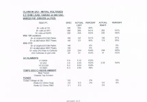
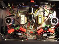
Quick update. The small driver PCB has now been made and installed first without the CCS upgrade for benchmarking. Works well with either the ECC99 or 5687 by moving 3 onboard jumpers. The small amount of noise has gone and without input is now pretty much silent with 97dB speakers. Voltages also better. See attached.
Will let it run for a day or two then instal the CCS which will allow tuning the driver plate loads etc.
Dave
Attachments

Hello,
I am in the process of sourcing parts for this build and noticed a descrepency between the parts list at the end of the article (here: http://www.hagtech.com/pdf/clarionarticle.pdf ) and the schematic.
The schematic shows a 10K 10 watt resistor at R7 where as the parts list shows 6.8K 10 watt.
I am bit shocked by low resistor values in driver and grid 2a3. This will be a bit bass limited, since all those nearby components are like signal divider.
At mids or treble cap will be like a short circuit, but not at bass.
Tks hpeter
Don't be shocked. Just answer a question. Have you built this amp?
And had a listen? I guess not so any comments are theory.
Great believer in first building an amp design as presented. Apart from obvious errors. If only out of respect for the designer. Jim Hagerman has been a respected designer for many years.
Been in this hobby a long time and believe me what you see on a ‘scope or in calcs doesn’t always match what you hear. Example: this amp has some overshoot on both leading and trailing square wave traces. Sine to 10Khz perfect. Purists may say no. Isn’t it about how it sounds? With your many other items that affect the result? There are many but particularly source quality (rarely discussed) and speakers. Quality of input is to me the one thing you have to get right.
This amp has been neglected. It is simple yet produces amazing results after getting the rest right.
As for use of 330R in key positions that was his choice and so should be respected. Jim is not the only one – many more. Another is respected designer John Broskie in his Aikido all in one 5687 pre using 330R. John says you can use up to 1K. If that is your thing then go ahead. Just don’t complain a design is wrong. Hope this helps.
Dave
The CCS plate loads are now in and operational. There are subtle differences in the sound – all good but nothing major as you would expect at this level. Hard to explain but probably cleaner with a little more volume. The amp has virtually no noise or hum, great dynamics and bass. Compared to 6 other tube amps owned - PP, OTL and SET. Overall this amp is a keeper.
For the modest investment would say go with the CCS. If only to allow easy adjustment of plate current particularly while listening in the early stages.
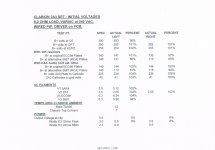
As an axample see attached final voltage readings where the 5687 comes in lower than the ECC99 when set for the 99 at 12ma. With the CCS it’s easy to adjust either anywhere you like. Until happy.
Dave
For the modest investment would say go with the CCS. If only to allow easy adjustment of plate current particularly while listening in the early stages.
As an axample see attached final voltage readings where the 5687 comes in lower than the ECC99 when set for the 99 at 12ma. With the CCS it’s easy to adjust either anywhere you like. Until happy.
Dave
Attachments

Hello all,
This thread has been pretty much dead for years, I know. For the past 18 years I have been dreaming of building my own 2A3 amp ever since I bought and built my Bottlehead Foreplay 2 preamp. I love the sound of tube audio. After 18 years I finally decided to actually start a build. Hagerman article seemed a great starting point with the concept of one stop shopping, although, I do want to deviate slightly from his “shopping list” provided from Antique Electronics Supply. Considering my lack of knowledge (ignorance) of electronics I was hoping someone would be able to help me make a couple small adjustments.
The bulk of the items I have purchased through Antique Electronics Supply, but I would like to purchase the transformers from Edcor. I don’t know if they are any better or worse than the ones spec’d but it is what I would like to do and if anyone has a valid reason why not, I am all ears. Keep in mind that I am also trying to keep cost to a minimum.
I’ve found a what I believe to be comparable power transformer. The Edcor XPWR179. Hagerman spec’d the Hammond P-T273DZ
117Vac
700v CT @ 103ma
6.3v CT @ 3A
5v @ 2A
The Edcor XPWR179 specs are: EDCOR - XPWR179
120Vac
700v CT @ 200ma
6.3v CT @ 5A
5v @ 3A
My first question is, will I be able to use this Edcor tranny without modifying the rest of the circuit design with the additional current of the XPWR179?
Secondly, and similarly I would like to try to use the Edcor GXSE output transformer. The Hagerman Spec’d output transformer is a One Electron 3000 ohm which Edcor does not have this impedance in the GXSE model. Edcor offers a 2.5k or 3.5k model. Which would best fit the application? I do not know what the difference in impedance will result. If it is of any use, this amp will be used to feed my Fostex FE167E (94db 8ohm) full range speakers that I build 16 years ago. I plan to soon build a set of backloaded horns using a similar and readily available Fostex driver. The Edcor output transformers I am looking at are linked below.
EDCOR - GXSE10-2.5K
EDCOR - GXSE10-3.5K
All help is greatly appreciated! I will gladly post up progress photos as this project comes together.
You could use the Edcor power trans. If the voltage end up slightly higher due to manufacturing and/or lower internal resistance, just adjust R1 and R4 (100R) for the output stage and R2 and R5 (2.2K) preamp/driver stage. Typically, you might end up doing that even if you use the same source and part.
I would use the 3.5K output transformer. To compensate for the slight loss of power I would increase 2A3 plate current to 60mA. You can do that by adjusting R11 (680R). You might even end up with a little less distortion this way.
I would use the 3.5K output transformer. To compensate for the slight loss of power I would increase 2A3 plate current to 60mA. You can do that by adjusting R11 (680R). You might even end up with a little less distortion this way.
Thank you so much for the feed back! I just finished drilling out the chassis for the tube sockets, terminals and power plug. I did not like the placement of the lamps from Hagerman’s layout, I feel like they should all be visible. Might as well!
I am not electrical engineer, but I have a fair understanding of schematics, so long as they are labeled properly (I do read construction plans for a living). I do not know how to design a circuit or understand what the individual components actually do individually, or collectively. I am however good at picking up details. I immediately picked up on the resistor difference that was noted in the very first post. Point of my rambling is I have been staring at the Clarion schematics from Hagerman trying to visualize the circuit and how It all comes together. At the 2.5v filament transformers, what am I missing. Does he assume you know the rest of that circuit? My limited understanding is telling me that is only showing half of the transformer, the primary. Where is the next in sequence of connect the dots?? Is the output of this directly applied to the filament pins? Or...?
Another question I have, is Pot. No not THAT, potentiometer.... again, I am ignorant. Where would one be inserted into this design and what Ohm rating should be used? Is it better to run one double pole or two singles? I do plan to feed this with my Foreplay 2 preamp.
Back to the filament transformer, I see that the original design has two filament transformers at 2.5v 2.5A. Is there any reason I couldn’t use a single 5v center tapped at 2.5v? I don’t know how this would affect the design of using the lamps integrated into the circuit to reduce the voltage. Any input?
I am thinking that using the Edcor tranny below would help me with space constraints: EDCOR - LVP5-2
This would also save a few $$’s for my tube budget...
Really looking forward to start slinging soldier! It’s been a few years.
- Jon
> (I do read construction plans for a living)........ At the 2.5v filament transformers, what am I missing. Does he assume you know the rest of that circuit? My limited understanding is telling me that is only showing half of the transformer, the primary. Where is the next in sequence of connect the dots?? Is the output of this directly applied to the filament pins? Or...?
An architect may draw a foundation, and a first floor, and a roof, and never tell you they go one on top of the other. A carpenter, by his second job, should know this. Does this floor fit on this foundation? Does this roof fit on top?
Likewise tube-guys "should know" that filaments get power from somewhere, and look for the some-where. It would be nice if we all had Mentors. Or started with $13 projects where a mistake is not a big boo-hoo. Alternatively you can study several similar plans on this internet (though many will "assume" the builder knows something).
Attachments
I would use a 100K (or 50K) potential-meter, low enough not picking up too much noise and high enough for a tube based signal source to drive. Dual single or one double gang is up to you. If you are the type hardly touch the volume control on the amp, dual single come with built in balance control. If you adjust volume all the time, a double gang volume control is a lot easier.
I assume, you mean adding a volume control.
I assume, you mean adding a volume control.
Last edited:
Back to the filament transformer, I see that the original design has two filament transformers at 2.5v 2.5A. Is there any reason I couldn’t use a single 5v center tapped at 2.5v? I don’t know how this would affect the design of using the lamps integrated into the circuit to reduce the voltage. Any input?
I am thinking that using the Edcor tranny below would help me with space constraints: EDCOR - LVP5-2
You can not use a single 5V xfmer with a center tap at the 2.5V to replace two 2.5V transformer. This will short out the signal path between the left and right channel.
Check your power transformer specifications:
Is the filament winding 6.3V?
. . . Or, less likely is it 12.6V?
If it is 6.3V, the Hagtech Clarion schematic at your post #1 is wrong.
The ECC99 wired properly for 6.3V requires you to tie pins 4 and 5 together.
Then apply one end of 6.3 volts to pin 9 and the other end of 6.3V to the tied pins 4&5.
The proper way to wire the ECC99 filament for 12.6V is to apply one end of 12.6V to pin 4, and the other end of the 12.6V to pin 5.
Now, as to those resistors you got:
ECC99 wired for 6.3V filament draws 0.8Amps
0.8 Amps through 0.47 Ohm = 0.376 Volt drop per resistor, 0.752V total.
0.8 Amps through 0.57 Ohm = 0.456 Volt drop per resistor, 0.912V total.
ECC99 wired for 12.6V filament draws 0.4 Amps
0.4 Amps through 0.47 Ohm = 0.188 Volt drop per resistor, 0.376V total.
0.4 Amps through 0.57 Ohm = 0.228 Volt drop per resistor, 0.456V total.
The question is, how much voltage comes off the filament winding with all the following factors:
Your Local Power Mains Voltage. 117V, 120V, 123V, etc.
Your Power Transformer Primary voltage rating, 115V, 117V, 120V, etc.
The Load current rating of the 6.3V winding (or 12.6V winding), 2A, 3A, 5A, etc.
The Load of the ECC99 filament puts on the filament winding.
All of that determines what the voltage is from the filament winding (the exact voltage under actual load of the "6.3V" or "12.6V" winding).
Those resistors are there to adjust the voltage at the filament as close as can be to 6.3V (or 12.6V).
I bet both the 0.47 Ohm and 0.57 Ohm resistors will put the voltage within +/- 10% of the ECC99 nominal filament voltage.
Last edited:
R11, 680 ohms, is the individual Self Bias resistor for One (1) channel of the amplifier.
The 2A3 tubes should be individually self biased (including the other associated parts, such as the bypass caps).
That absolutely requires Two (2) individual 2.5V filament windings.
That amplifier is a good design.
Build it as designed, and enjoy listening to it.
The 2A3 tubes should be individually self biased (including the other associated parts, such as the bypass caps).
That absolutely requires Two (2) individual 2.5V filament windings.
That amplifier is a good design.
Build it as designed, and enjoy listening to it.
An earlier post mentioned the low resistance for the 2A3 Grid resistor.
At 33k Ohms and 0.47uF, the -3dB point of that RC coupling is 10Hz, which is only - 1dB @ 20Hz.
You will be lucky to get both the output transformer and the 2A3 Bypass cap to be no more than -1 dB @ 20 Hz each.
That would put the total amplifier response at -3 dB at 20 Hz.
Please list the loudspeaker you are using that is only down -3dB @ 20 Hz.
That would give your system a total response of -6dB at 20Hz, lots better than 90% of the systems I have ever heard.
Lol, you skipped over to this thread! I was scratching my head there for a minute!
I may need to read your posts 20 times before I grasp them.
I can get a read on what voltage at my [current] home, and report back.
As for the Speaker I plan on using is the Fostex FE167E:
FE167E Enclosure plans I have a powered sub I use sometimes to fill in the low end, and have been thinking to add a tweeter to to fill in the top end. Input/suggestions is very welcome as there as well.
I will post this over on my thread too.
- Home
- Amplifiers
- Tubes / Valves
- Hagtech Clarion 2A3 SET