The voltage drop of the original 3-diode string sets the operating currents for the input and voltage amplifier stages. It is important that this does not change. The input stage transistors on the DH-200 operate at approximately 1 mA. That current through R6 and R17 sets the reference voltage for the VAS stage (2.2V). The VAS stage is very sensitive to this voltage. VAS current is controlled by the voltage across R27 and R33 (100 ohms), which should be no more than 1V. If the DH-200 VAS operates at ~ 10 mA then the VAS transistors are dissipating ~ 1/2 watt. Q8 and Q11 are the VAS transistors, a pair of metal can types with clip-on heat sinks. One of the changes made on the DH-220 was to reduce the bias currents of the input and VAS stages a bit, using different resistor values. I assume your red LED drops about 2 V, but if it is above that you may be running with a hot VAS stage.
OK, thanks all for the input. I understand the IPS and downstream a little better now. But I still don't understand why a single LED would perform better as a voltage reference than a string of 3 standard diodes.
I found some links here on DIY regarding an ultra-low noise 2.5V reference circuit which uses an LED, (developed by Walt Jung). I don't fully understand it, but I am attaching his own description. This seems similar to what's being used in this modded 200.If so it seems a good improvement to make to a circuit. Please correct me if I'm wrong.
Ron
Attachments
Actually I have a correction to make. I discovered another one of the "enhancements"...although C1 remains attached to the board it is completely bypassed with a wire. Is that part of why is sounds so good, "the best sounding capacitor is no capacitor"?But strangely C1 appears to be stock...
Ron
Is the unit thus vulnerable to DC input voltage? Do most sources feeding an amp have DC output protection?
Maybe I should add some really good input caps to see if I keep the same sound.
Ron
OK, thanks all for the input. I understand the IPS and downstream a little better now. But I still don't understand why a single LED would perform better as a voltage reference than a string of 3 standard diodes.
I found some links here on DIY regarding an ultra-low noise 2.5V reference circuit which uses an LED, (developed by Walt Jung). I don't fully understand it, but I am attaching his own description. This seems similar to what's being used in this modded 200.If so it seems a good improvement to make to a circuit. Please correct me if I'm wrong.
Ron
One difference between a strong of 3 diodes and an LED is the temperature coefficient. Some of these issues, including Walt's reference, are discussed in Chapter 2 of my second edition.
Cheers,
Bob
One difference between a strong of 3 diodes and an LED is the temperature coefficient. Some of these issues, including Walt's reference, are discussed in Chapter 2 of my second edition.
Cheers,
Bob
Thanks, good to know, especially since I have your book!
I will have a look. It's a perfect book for me--much is understandable, but there's a lot I need to grow into.
The voltage drop across the LED is 1.65V. The voltage drop across R12 is 1.056, and R12 measures 554Ohm (nominal 560 Ohm)--this gives current of 1.906mA.The voltage drop of the original 3-diode string sets the operating currents for the input and voltage amplifier stages. It is important that this does not change. The input stage transistors on the DH-200 operate at approximately 1 mA. That current through R6 and R17 sets the reference voltage for the VAS stage (2.2V). The VAS stage is very sensitive to this voltage. VAS current is controlled by the voltage across R27 and R33 (100 ohms), which should be no more than 1V. If the DH-200 VAS operates at ~ 10 mA then the VAS transistors are dissipating ~ 1/2 watt. Q8 and Q11 are the VAS transistors, a pair of metal can types with clip-on heat sinks. One of the changes made on the DH-220 was to reduce the bias currents of the input and VAS stages a bit, using different resistor values. I assume your red LED drops about 2 V, but if it is above that you may be running with a hot VAS stage.
The voltage across R27 = 844mV, R=100 Ohm = nominal value--gives 8.44mA.
The drop across R6 & R7 = 2.053 and 2.013 respectively, giving 0.943 mA and 0.929 mA, (close to your expectation).
These numbers seem pretty in line with expectation, no? But I'm sorry it's not clear to me, where do you expect to see the 2.2 volts?
These bias numbers are higher than the DH-220? Are you referring to the PC-10 board? Some say the higher bias sounds better--maybe that's why somebody earlier in this thread said they preferred the sound of the 200 vs. the 220 or 500.
Ron
The voltage drop across the LED is 1.65V. The voltage drop across R12 is 1.056, and R12 measures 554Ohm (nominal 560 Ohm)--this gives current of 1.906mA.
The voltage across R27 = 844mV, R=100 Ohm = nominal value--gives 8.44mA.
The drop across R6 & R7 = 2.053 and 2.013 respectively, giving 0.943 mA and 0.929 mA, (close to your expectation).
These numbers seem pretty in line with expectation, no? But I'm sorry it's not clear to me, where do you expect to see the 2.2 volts?
These bias numbers are higher than the DH-220? Are you referring to the PC-10 board? Some say the higher bias sounds better--maybe that's why somebody earlier in this thread said they preferred the sound of the 200 vs. the 220 or 500.
Ron
...I should mentions that R6 and R7 measured 2176 Ohm and 2166 Ohm respectively, (nominal 2.2k).
The voltage drop across the LED is 1.65V. The voltage drop across R12 is 1.056, and R12 measures 554Ohm (nominal 560 Ohm)--this gives current of 1.906mA.
The voltage across R27 = 844mV, R=100 Ohm = nominal value--gives 8.44mA.
The drop across R6 & R7 = 2.053 and 2.013 respectively, giving 0.943 mA and 0.929 mA, (close to your expectation).
These numbers seem pretty in line with expectation, no? But I'm sorry it's not clear to me, where do you expect to see the 2.2 volts?
These bias numbers are higher than the DH-220? Are you referring to the PC-10 board? Some say the higher bias sounds better--maybe that's why somebody earlier in this thread said they preferred the sound of the 200 vs. the 220 or 500.
Ron
I just a hobbyist and not a tech, so I am unfamiliar with the various revisions to the Hafler boards. The manual for the DH-200 indicates it is the PC-6, the DH-220 manual is for the PC-19c.
The 2.2V would was based on having 1mA through R6 and R17 (you measured this at a bit over 2V). That voltage would also appear at the base of Q7 or Q10, which are the helper transistors for the positive and negative sides of the VAS. That reference voltage controls the VAS current. All the numbers you measured are reasonable. Your red LED sets a slightly lower voltage than the three diodes it replaced, so the IPS and VAS currents are slightly lower. But the difference is not enough to cause any problems.
The "higher bias sounds better" stuff is referring to the bias (idle) current through the output MOSFETS when no signal is present. The adjustment for this is part of the VAS, and any change in VAS current will affect this too. The idle current for the MOSFETS is controlled by a potentiometer, and in the schematic P1, R29, R30, and Q9 make up the "VBE multiplier" which sets the bias voltage for the output driver transistors Q12/Q13.
That said, the VAS current does not have a direct relationship to the output stage idle current. The VBE drop of Q9 will change slightly depending on the amount of current through the transistor, temperature, etc. But a 15% change in VAS current will only produce a very small change in VBE, which will affect the output bias current.
The DH-200 manual does not have any instructions for adjusting the bias, but the DH-220 manual does. It is difficult to measure directly without removing parts, so the manual recommends replacing the fuse for that circuit board with your current meter. The recommended setting is 275 mA, which is the total current drawn by the circuit board, resulting in a bias current of near 250 mA. Raising this will make the amp run a bit hotter, but is one modification said to improve sound.
DH-220C update
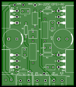
As part of our DH-220C testing Bob Cordell suggested that it would be nice to have a pcb installed between the HS ears for the OPS, so that it is a clean way to add some components that were otherwise flying.
With Bob's help, I have designed this small pcb and we are in the process of ordering some to test.
One addition is a means to measure OPS bias current. Also added are the gate series R's, a source zobel network, extra filtering.
Since I do not own a DH-220, I made the pcb so that one can use these designs without one. I made a footprint for plastic fets so that this design can be used without the DH-220 chassis.
This OPS pcb is not necessarily only for DH-220C, it could be used in the stock unit as well or another chassis arrangement, such as the DIYAudio chassis. mechanical details need to be figured out, but trying to make these designs as universal as possible.
Attachments
But I still don't understand why a single LED would perform better as a voltage reference than a string of 3 standard diodes.
All pn junctions have roughly the same temperature coefficient, its set by the physics, and stringing them in series will multiply the temperature coefficient by the number of pn junctions.
Thus having a single pn-junction from a material with a 3V bandgap will fare better than 3 pn junctions from a meterial with a 1.1V bandgap - the voltage will be less sensitive to change as the enclosure / pcb warms up.
To give a little bit more detail, the forward voltage of a pn-junction will typically be roughly around 0.4V below the bandgap voltage at typical small signal current densities (where the resistance of the material can be ignored). This voltage difference depends linearly on absolute temperature (for constant current).
This comes straight from the statistical mechanics of a voltage barrier, the bandgap being the barrier voltage V0, and the probability of a random charge carrier jumping the barrier being proportional to exp (- q(V0 - V) / kT),
where q = charge on electron, k = Boltzman's constant, T = absolute temperature and V = voltage of the charge carriers approaching the barrier.
Note that silicon has a bandgap of about 1.15V, and forward voltages tend to be 0.6 to 0.75V, GaN based blue LEDs have a bandgap of 3.4V, and a typical forward voltage around 3 to 3.2V (although such LEDs have a more complex structure with quantum wells, but the basic physics still applies).
Thanks Mark.Thus having a single pn-junction from a material with a 3V bandgap will fare better than 3 pn junctions from a meterial with a 1.1V bandgap - the voltage will be less sensitive to change as the enclosure / pcb warms up.
.
I'm pretty new to audio circuit topology study, but even in my short foray into this subject I've seen many instances of the 3-diode arrangement, the purpose of which I now better understand. So my next question would be why the use of the single LED vs. the 3 didoes is not more common. Are the LED's considered less robust than the diodes?
Thanks,
Ron
Yes it would be much easier than PTP with those added components. But if one wanted to use the existing TO-3 FETs, would they be wired into the PCB? I assume the extra length on the leads would not be a problem.This OPS pcb is not necessarily only for DH-220C, it could be used in the stock unit as well or another chassis arrangement, such as the DIYAudio chassis. mechanical details need to be figured out, but trying to make these designs as universal as possible.
That is the idea that we will try out.But if one wanted to use the existing TO-3 FETs, would they be wired into the PCB?
I have both a 220 and a xl280, both untouched since original, and reading this thread I am not much further ahead in understanding what Mods/upgrades would make a real difference.
These are old units showing wear and tear, but they are both dead quiet with flat freq response...working well.
I will probably just replace a few critical caps, trimpots, switch, and clean the units thoroughly...
New driver boards are intriguing, but MC costs more than good used or even new amps, and I am unconvinced the drivers boards would make that much difference. Is there anything better that subjective opinion that they really do make a noticeable difference?
I have both a 220 and a xl280, both untouched since original, and reading this thread I am not much further ahead in understanding what Mods/upgrades would make a real difference.
These are old units showing wear and tear, but they are both dead quiet with flat freq response...working well.
I will probably just replace a few critical caps, trimpots, switch, and clean the units thoroughly...
New driver boards are intriguing, but MC costs more than good used or even new amps, and I am unconvinced the drivers boards would make that much difference. Is there anything better that subjective opinion that they really do make a noticeable difference?
Hi Peter,
These are good and fair questions, especially where subjective sound quality comes into play. The DH-220C PCBs and BOM should be available soon. You may want to wait and see what people have to say who have built it. There is also a presentation on it that I did at Burning Amp 2016 that you might want to take a look at. It is available on the Linear Systems Youtube site.
Cheers,
Bob
Thanks Bob, I’ll look at the presentation. I’m not yet up to speed with who has done what, so I appreciate the pointer!
I want to know why things are markedly improved but I won’t be shy to adopt once I understand that.
I will admit to being dangerously semi educated on this, having been a Switched mode power supply designer many years ago...we mused at the time (1980’s) about using magnetic amp toroids to produce a super efficient audio amp, but never took it further. Don’t know enough yet.
Peter:
Did you play around much with the "Excelinear" trimmer cap on the XL280 at all and notice any changes in your system sound? Just curious ....
I always thought is was an interesting feature.
mlloyd1
Did you play around much with the "Excelinear" trimmer cap on the XL280 at all and notice any changes in your system sound? Just curious ....
I always thought is was an interesting feature.
mlloyd1
Peter:
Did you play around much with the "Excelinear" trimmer cap on the XL280 at all and notice any changes in your system sound? Just curious ....
I always thought is was an interesting feature.
mlloyd1
While I have been tempted to play with that, I haven’t...mostly because I have been using the XL as a bass amp only up to about 200 hz. But that’s why I want to clean and replace any tired parts...so my options open up.
I will have that, the 220, an arriving gfa535 II and I am mostly done with a complete tear down and rebuild of a disastrously maintained/screwed up Luxman L100U.
So I will have choices. Too many ideas, too lazy to get em all done. Story of my HiFi life.
I have both a 220 and a xl280, both untouched since original, and reading this thread I am not much further ahead in understanding what Mods/upgrades would make a real difference.
These are old units showing wear and tear, but they are both dead quiet with flat freq response...working well.
I will probably just replace a few critical caps, trimpots, switch, and clean the units thoroughly...
New driver boards are intriguing, but MC costs more than good used or even new amps, and I am unconvinced the drivers boards would make that much difference. Is there anything better that subjective opinion that they really do make a noticeable difference?
Peter,
I have a couple XL-280's I'm in the processing of modding, as well as several DH-200's, a couple DH-500's and a P500. For an "original" XL-280 I would consider:
- Replacing the electrolytic caps on the input board. If original these caps are 30+ years old, and could likely need replacing (sounds like you are already doing this)
- Additionally you could consider upgrading some of the other caps. Though not likely to have gone "bad", there may be higher quality ones now available which were not available in the late 80's
- Replace and/or upgrade PSU main caps (currently 4 x 7.8k uF). You can find ones now with twice the capacitance which fit in the same space. Look for quality low-ESR, high ripple caps
- Consider some of the PSU design improvements presented by Bob Cordell in chapter 19 of his new book:
- Addition of high-quality bypass caps across reservoir caps including a 100uF electrolytic + lower value film caps
- Addition of Zobel network
- Add small resistance between capacitor banks to create RC filter which can substantially decrease ripple amplitude
- The higher voltage, lower current secondary on the XL-280 transformer feeds the input and VAS stages of the circuit. This secondary voltage is rectified via 4 x 1N4003 discrete diodes. One could consider replacing these with a set of faster, soft-recovery type diodes like Vishay HEXFRED, (Cordell chapter 19, section 5).
Generally speaking one of the most exciting possibilities I see at the moment for upgrading vintage amps, (while I wait for the release of the Cordell boards), is the implementation of an "ideal rectifier" using the LT4320 chip. A lot of effort and money can be spent getting rid of noise generated by the standard bridge rectifier, but all this noise can be eliminated at the source by using the LT4320. However, in the case of the XL280 the 4320 cannot be used without changing the transformer. I may consider doing this depending on the results I get from the other mods I plan to do (as time permits
 ).
).there is no space to put many changes, but these all fit and help
an Ixsys high speed diode bridge.
Change the filter caps to larger, but you’ll need a turn on thermistor to save the power switch
Put 2 Quasimodo CRC snubbers on the diode bridge - one on each winding to center tap
an Ixsys high speed diode bridge.
Change the filter caps to larger, but you’ll need a turn on thermistor to save the power switch
Put 2 Quasimodo CRC snubbers on the diode bridge - one on each winding to center tap
Put 2 Quasimodo CRC snubbers on the diode bridge - one on each winding to center tap
Yeah, I was going to add the snubber. I plan to measure my XL-280 transformer soon, so I will share the values I obtain...unless somebody already has those.
- Home
- Amplifiers
- Solid State
- Hafler DH-200/220 Mods