No, your comments don't irritate. I agree with most of them. But things are not always as they seem. For example, your diagnosis of C5 being the cause of no gain was wrong. The problem was C1. I still have a few matched diff sets but cherish them and am not going to give them up for free, which is why I would have to check with the guy before installing them. He and I had this agreement before I lifted the lid. I, also, used to routinely replace the diff set but often found the problem was elsewhere so am reluctant to start throwing parts at a circuit. This is why I first try some used parts from the bin. I am doing an el cheapo job for this guy and only charging for my out of pocket expenses plus what amounts to about $5 per hour. I wouldn't call this a business.
Actually, instead of replacing the diff set I may put a 100kohm pot across the rails and feed the wiper voltage through a two meg resistor to R3. This is a useful hint from Walt Jung, TAA 1/83. I've used it twice with great success and it's cheaper and quicker than replacing 4 Qs with matched sets -- at least for me.
Actually, instead of replacing the diff set I may put a 100kohm pot across the rails and feed the wiper voltage through a two meg resistor to R3. This is a useful hint from Walt Jung, TAA 1/83. I've used it twice with great success and it's cheaper and quicker than replacing 4 Qs with matched sets -- at least for me.
Attachments
"For example, your diagnosis of C5 being the cause of no gain was wrong."
That was me, not Chris.
I mentioned C5 as most technicians miss it, and it does cause loss of gain.
C1 causes loss of input signal, not the same thing, and most technicians check it early on in the repair process.
That was me, not Chris.
I mentioned C5 as most technicians miss it, and it does cause loss of gain.
C1 causes loss of input signal, not the same thing, and most technicians check it early on in the repair process.
You are correct. Sorry I mixed up comments from various messages. I used to do a lot of mods to Haflers 15-20 years ago but since acquiring an MC modded hafler with the PA-3C circuit cards I have quite messing with Haflers and with mods. I backed into sleuthing out a problem in this dumpster diving acquisition and had to refresh my memory on lots of aspects of the DH-200 circuit.
Comments from you and others helped a lot. Hopefully, I am now mostly through with messing with this amp. I really hate working on the DH-200 as it is so difficult to do anything with the back panel items because of the shape of the chassis.
Later.........
Comments from you and others helped a lot. Hopefully, I am now mostly through with messing with this amp. I really hate working on the DH-200 as it is so difficult to do anything with the back panel items because of the shape of the chassis.
Later.........
Hi Dick,
I agree with djk on the C5 call as I've run into so many instances where it's bad. Also C1, but that isn't as often. I would think you would check those due to your high amount of experience with these. So I'm just a guilty as djk here, silently agreeing.
I understand your approach. Somehow you got yourself behind the eight ball on this repair. I hope your customer understands the effort you are putting in.
Hi djk,
-Chris
I agree with djk on the C5 call as I've run into so many instances where it's bad. Also C1, but that isn't as often. I would think you would check those due to your high amount of experience with these. So I'm just a guilty as djk here, silently agreeing.
I understand your approach. Somehow you got yourself behind the eight ball on this repair. I hope your customer understands the effort you are putting in.
Hi djk,
Not possible to disagree with you!I mentioned C5 as most technicians miss it, and it does cause loss of gain.
-Chris
HaflerDH200mods cont....
In post 429-430 I made a small error in describing the predrivers as 5550 and 3440
Of course I should have said 5415 and 3440 TO5 types the 5550-5551 is a TO92
case and is used for low current.Sorry about that but thats what you get for writing these ideas up in the middle of the night! Next on the agenda is to consider the power supplies, but first to introduce the use of another pair of O/P devices on the heatsink. there are three options here, depending upon your handyness with drills and TAPS. You can go for the same devices and fix in the same way with holders,
or you can replace the bottom pair of J49 K134 with a pair of double die devices
ECF20N16,ECF20P16, which is equivelent to two pairs being 16amp devices, but on balance i suggest the TO3P devices J162 K1058 because they can be fixed with just
one M3 screw each{with mounting kit} then hard wired to existing components
NOTE, this mod will need the thermal breaker to be moved elsewhere, personally
I do away with these altogether,It hardly warrants putting heavier mains cables in these amps when you have two+ foot of flimsy cable all around the inside of the
case, with the added contact resistance of the thermal breakers to mess everything up,the mosfets are self limiting anyway with temperature rise and by 75degrees
[ the breaker temp] your current from the amp will have dropped to about a third
and thereby reducing the temperature on the heatsinks...If you still want a warning of temperature place the breakers on the heatsinks near the front of the amp and affix two LED's in a holder on the front panel ,one green the other red
I.E port and starboard, left and right for each heatsink wire the LED's directly across the breakers then from one side of the breaker a resistor about 12000ohms
12k to the power supply rails,with over temp the LEDS will light and tell you which
heatsink is overheating, personally unless you intend to abuse these amps I wouldn't bother.Next consider fitting in the case an extra pair of 10,000mfds caps
80volts working, Gemcon or Elna types, they will work okay with the existing caps
but you may have to juggle the position of the original caps to fit, or even move the bridge, don't forget to decouple the new caps with 2.2-4.7mfds across them.
All this will give this amp a significant improvement in bass control, and will handle
lower speaker impedances in a much better way with other benefits of lower distortion and more zing....
more suggestions to follow.{I know , is there no end to these mods?}well no there is'nt actually
I am aware that some of these mods have already been implemented by others but I am trying to encapsulate most of them in a series to save people that are interested in hunting all over the place...Regards
from humble:
I'm a vinyl fan too so no debate from me on that.
I'm interested in PS mods as I believe that's one key item that often "separates the men from the boys" in the power amp arena.
I'm watching this thread and searching others for useful XL-280 "above sub-range" tuning info.
I play a lot of records and with my TL speakers with supertweeters the treble is simply astonishing makes compact disc sound very limited{in my opinion, so no debate please}. anyway there are a few more mods to come yet, but still using the same circuit, but more to do with the power supplies.
I'm a vinyl fan too so no debate from me on that.
I'm interested in PS mods as I believe that's one key item that often "separates the men from the boys" in the power amp arena.
I'm watching this thread and searching others for useful XL-280 "above sub-range" tuning info.
HaflerDH200modscont
The last post dealt with a very simple power supply improvement, the next step is to
consider changing the power transformer for a Toroidal type, the advantage of this
is that being low profile means that you can fit right above it on a piece of paxolin or
perspex sheet of suitable thickness set on stand-offs, a place to mount some serious
capacitance,I have used in this situation 60,000mfds of 80volt ELNA's, in two rows of three, terminals facing each other, using standard mounting hardware with L brackets bolted down to the paxolin..But you can go one step further with this idea
Using the standard size of 500VA toroid you can arrange to have some extra windings added to the standard split secondaries of 10-12 volts, or add these windings yourself which is actually quite easy using .71 MM enamalled wire, you can then consider building a stabilized early stage supply of higher voltage , say 10volts
DC more, this will then give the Hafler a little more power, up to 140watts, but
will significantly reduce the noise, an important consideration if you are using very
sensitive speakers, A standard 78-79 series regulators can be used for this regulated
supply, 12volt regulators with zeners of 2times 30volt pedestalling up to a total of
72volts [ with reverse diodes across the regulators of course] will do the job. When I did this years ago it was necessary to cut back the casework of the Hafler to get the transformer to sit as far forward as possible to fit everything in{there is a lip of about
half an inch top and bottom of the case which i nibbled away},Obviously this much
work is a challenge, but having done it myself and gained the satisfaction of pushing
the performance envelope of this{what was a simple amp} to something very worthwhile in audio terms was well worth the effort , now my monoblocs have taken over all based on the ideas that i have given.....Regards
DICK WEST,HAFLER OFFSET
HI Dick, had to laugh at this offset question, wanted to say 60mv THAT LOW, I've
had some much higher than that, as you now probably surmise, one trick that is always worth a try is to swap over the SAME I/P pairs 5551 with 5551 and 5401
with 5401 I/P side to Feedback side, sometimes this reduces the offset sometimes
makes it worse the suggestion of using a trimmer from the rails to the I/P pairs
is a good idea BUT the arrangement does need to be decoupled to stop power supply
variations getting into the I/P this will BE a small amount of + feedback otherwise,
have a look at the Hafler 220 arrangement, which uses a floating feed from the CCS
via a couple of 1n4148 diodes to swing the offset a small amount, Its main advantage is that the setting is less twitchy with more movement of the 1k setting
resistor, this is because the total voltage swing is just +,- 0.6 volts whereas a pot from the rails will be +,- 62volts
regards
Anatech verses diff pairs
Tut Tut my boy ,don't you think matching these I/P pairs has been tried?
I have wrestled with this anomally many times having bought many many
transisters of all the types used on the board and even when absolutely matched, you can still get an offset, sometimes unreasonably high I have even matched
the diodes in the CCS, sometimes when the matching is less good [within a beta
of 5 to 10] the offset is better, the only thing you learn from this exercise are new
swearwords, the only conclusion I came to was that because the predrivers often
had a very low gain, they PULLED the I/P diff pairs unevenly, and that these 3440,
and 5415 needed to be gain tested at say 10M/A in any event, as has already been suggested a simple balancing circuit will do the job, I have no doubt that HAFLER
underwent similar frustration with this problem hence the adjustment circuit used in the later 220 model {ANY suggestions from SLOWHANDS?}
The acceptable limit for offset is set at 50mv for the HI FI spec, fully symmetrical
designs always need more care generally to get lower offsets,It did not seem to compromise the performance of the Hafler even when the offset exceeded this 50mv
value so no point in worrying, just be happy that you have a UNIQUE amplifier,
[Strange ,peculiar, oddball, ha ha]
BUT CHALLENGING,
cheers
Tut Tut my boy ,don't you think matching these I/P pairs has been tried? I have wrestled with this anomally many times having bought many many transisters of all the types used on the board
Humble
I still have a couple extra sets, all closely matched, of devices for the DH-200 PCB. In the past I have rigorously (almost religiously) replaced the 4 input devices but sometimes the offset still persisted. That is why I went to the more "brute force" solution to inject some B± voltage to R3.
By decouple will a small film cap across the B± attachments to the variable resistor do the trick? This small film cap would be mounted between the two ends of the variable resistor. Is this what you mean by decouple?
Thanks for your comments......
Dick West DECOUPLE
Hi dick I can't quite recall your exact arrangement, however a simile circuit would be
some value up to 1mohm variable pot across the rails, the wiper of the pot feeding
a resistor up to 4.7mohms, then a further 4.7mohms to the I/P pair.From the junction of the two 4.7mohms decouple with a suitable capacitor a 0.22mfds to
earth the cap only needs to be about 50volts wkg the small X7R dielectric types are
fine from RS components but any mylar etc will suffice,point to note here,you are attempting to reduce a high voltage down to something much smaller a single turn pot makes it difficult to adjust, because the slightest movement gives large changes
in voltage, a better way to go is to use a 100kohm pot with 1mohm resistors
either side ,this is called padding the pot and gives a 10 to 1 ratio of movement, making adjustment much easier, also the higher value resistors [4.7meg] will
also help in this respect because they form a potential divider with the 22kohm
I/P resistor, these values are only suggestions, but the lower you go with the 4.7mohms the more difficult it is to zero, as you will no doubt find out, hope this answers your query.
regards
Hi Guys,
This is interesting. I've never ended up with high DC offset after matching the input transistors.
Mind you, I also match the 2N3440 and 2N5415 as well. Is it possible you have a leaky capacitor that's upsetting things?
-Chris
This is interesting. I've never ended up with high DC offset after matching the input transistors.
Mind you, I also match the 2N3440 and 2N5415 as well. Is it possible you have a leaky capacitor that's upsetting things?
Don't forget, I'm a technician. One rule is very simple. Never assume anything. No insult implied or intended.Tut Tut my boy ,don't you think matching these I/P pairs has been tried?
-Chris
Hi djk,
-Chris
I agree. That's why I match the other parts as well. Also, any temperature drift will be reduced with matched diff pairs over non-matched pairs.Even when everything does match, there will always be some drift with temperature.
-Chris
djk,Anatech,offset
Can we take it as read that these factors you mention have been taken into account
in attempting to improve the offset of these amps. The monoblocs of mine that I mentioned have 2% tolerance resistors throughout apart from a few VISHAYS with
tighter tolerances, now despite very careful matching of I/P pairs + diodes in ccs
+new high gain predrivers and drivers still left me with 29mv on one amp and 5mv
on the other, thats why I know new swearwords, like yourselves I had convinced myself that all this trouble would crack the problem once and for all but it didn't,
only reduced it, so like Dick am forced to to use a pot arrangement to get my zero
offset, just as a matter of technical pride, which will be the least complicated way of solving this problem, the only other way is to use a current servo feeding one of the
ccs's as me and my colleague used on our 100watt fully symmetrical design, which
gave us similar difficulties, of course i could put small pots of 100ohms in the emitter
circuit but that would not sound very good and therefore is ruled out, pots always seem to say you didn't do your homework well enough in the design stage although
I accept that it is sometimes a necessary evil.The reality of this situation is that we are really labouring over very little for as I said,Haflers with higher offsets than say
60mv didn't sound any worse than those with much lower offsets, that the amp lended itself very well to many improvements which rendered offsets immaterial
provided they didn't reach silly numbers,I drew the line at 75mv and then rematched
transistors, I did suspect that many of these amps were originally lower but that age
of components eventually took its toll, the amps are very old.
regards
Hi Humble,
Just curious, since I haven't run into this before.
1. Did you swap the matched pairs from side to side to see if the offset followed the pairs?
2. How do you measure beta and how do confirm the pairs are indeed matched?
This did happen to me, but it's always been a case of the input pairs being unmatched. I also had a case of one ccs transistor leaky that was cured when I replaced it.
I am not treating you like an idiot. I am attempting to help you and also understand what is going on.
I have recently built a jig to confirm matched pairs for both J-fets and BJTs. It works extremely well and I've been able to get much tighter matches with it. Basically, it's a ccs with selectable current, matched 10K precision resistors from base / gate to ground and a pair of matched 100R precision resistors from the collector / drain to the supply. The emitter / sources are tied together. I didn't like some of the answers it gave me, but it also explained a lot at the same time.
BTW, in case you were unaware. Vishay resistors are Dale after they were bought. Good parts but not magic.
-Chris
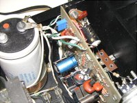
Humble
Check out my post #441. You can see the picture I posted of the arrangement. In the upper left hand corner of the PCB you can see the blue small multi-turn 100K pot, the wiper of which feeds R3 through a 2 meg resistor, and across the pot is a small film cap (on the back side of the PCB to help reduce any "noise" that might be riding on the supply rails.
This arrangement is not overly sensitive and a few turns can be used without making a huge difference in the offset. I don't have a signal generator or scope so can't tell about any noise it might introduce but it makes no difference in the sound, as far as I can tell.
It is a lot simpler and cheaper and faster than matching and installing several small transistors. I have done this in the past only to find the DC offset persisted. I am not motivated to throw a lot of parts into these old amps so my "fix" is suitable on a cost-benefit ratio.
Hafler included DC offset adjustment on the DH-220, partly because it was needed and partly because it helped reduce parts cost and time to match components in a production setting, plus it was a good sales feature.
For several years I used a dual mono DH-200 with polyprop caps tacked on all over the PCB. It made a good sounding amp. But, the Musical Concepts PA-3B beat the pants of anything I had around and it was a lot simpler to use.
Here is the extreme amateur mods can go to:
Attachments

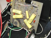
Here is an amp with extra smaller electrolytics bypassing main caps and with polyprop bypasses on each channel placed behind the PCB. The pair of 100 uF on each PCB were replaced with some Panasonic 220 uF caps.
These things make the amp sound a little different and, of course, I think a little better.
These things make the amp sound a little different and, of course, I think a little better.
- Home
- Amplifiers
- Solid State
- Hafler DH-200/220 Mods