Hi Ozark HiFi Doctor,
Heck, been working on these old amplifiers for over 4 decades professionally. Nothing wrong with doing that as long as you are actually improving the performance. The only way to do that is measure before and after performance with state of the art equipment along with the knowledge of what good measurements are. That and listening tests provide guidance.
Some work I have seen done actually impairs the performance of many products, particularly with Hafler products (including preamps). That work has been performed at a high price tag. That's a crime as far as I am concerned.
I like what Bob Cordell, Dave and Rick are doing. Good, clean reliable work. Performance is improved and it is well engineered.
Nothing wrong with maintaining and (actually) improving the performance of old equipment. I'm a strong believer in that, and kudos to all who do good clean work at a fair price.
-Chris
Hi petr,
Are all of these graphs from simulation, or have you build and measured the DH-220C?
What is your criteria for an amplifier failing the Hafler SWDT (straight wire with gain)?
What is "speed distortion" and how did you measure it?
Cheers,
Bob
Hi, Bob!
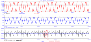
Graphs obtained by simulation using your transistor models Hafler's SWDT test measures vector errors (for more details, see the book I got "Operational Amplifiers by Jiri Dostal"
According to David Hafler's ideas, for the absence of noticeable distortions, the difference signal between the scaled input signal and the output signal should be no more than -70 dB (0.01%).
To fulfill this condition, the signal propagation delay must be negligible. The amplitude of the difference signal (vector errors) is calculated using the formula I got it:
a = 2πA * tPD / T
where
a - the amplitude of the differential signal (vector error)
T - is the signal period, μs;
A - signal amplitude at the outputs of the amplifiers, V
tPD – time Propagation Delay (Group Delay), μs
From this formula, you can calculate the required propagation delay tPD for the SWDT test condition. For higher frequencies of the audio range, the delay is several ns, but not hundreds.
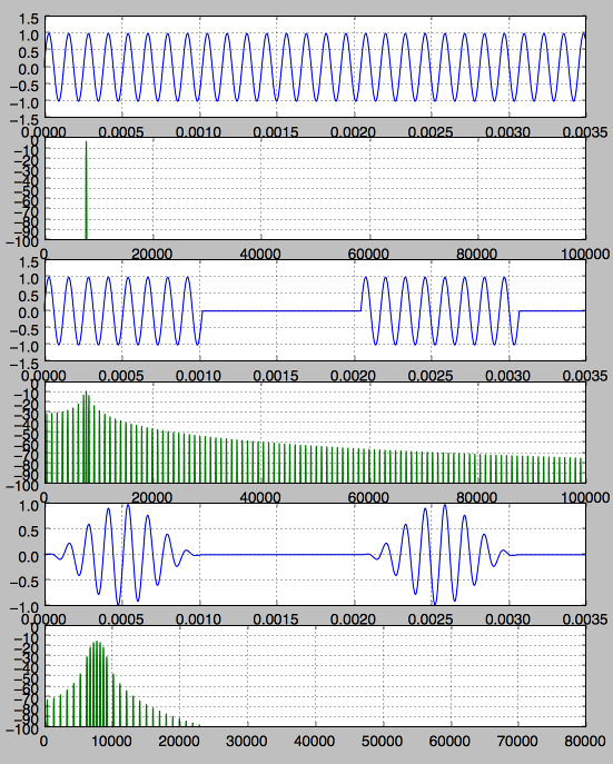
Speed distortions occur at any deviation of the signal from the sinusoidal one. On a purely sinusoidal signal in the steady state, speed distortion does not appear. And although Hafler introduced the signal propagation delay adjustment to the XL-280 amplifier and it can be set to almost zero or even negative value for a specific frequency, nevertheless, his amplifier actually has high speed distortions that are easily detected using a triangular signal (using any signal other than a sinusoid: rectangular, 1/3 octave noise).
Speed distortion is detected by subtracting the output from the scaled input time delayed tPD.
Hi Petr,
IIRC, Haflers test was basically a subtraction of scaled output from input; basically the scaling was adjusted for a null. A headphone was used to listen to the resulting difference signal, with one wire connected to the input and the other wire connected to the scaled output. The idea was to literally listen to the distortion, not measure the difference with an instrument. The key is that phase differences caused by signal propagation through the amplifier only impair the subtraction at very low and very high inaudible frequencies. A phase difference causes a non-zero difference, but a phase difference is not nonlinear distortion. Any amplifier with a finite bandwidth will show a difference with this test.
It also appears that the speed test is a test that normally yields a waveform distortion only due to phase differences, even if there is no nonlinear distortion. Mere propagation delay through the amplifier is of no consequence and cannot be heard.
Cheers,
Bob
Hi Petr,
IIRC, Haflers test was basically a subtraction of scaled output from input; basically the scaling was adjusted for a null. A headphone was used to listen to the resulting difference signal, with one wire connected to the input and the other wire connected to the scaled output. The idea was to literally listen to the distortion, not measure the difference with an instrument. The key is that phase differences caused by signal propagation through the amplifier only impair the subtraction at very low and very high inaudible frequencies. A phase difference causes a non-zero difference, but a phase difference is not nonlinear distortion. Any amplifier with a finite bandwidth will show a difference with this test.
It also appears that the speed test is a test that normally yields a waveform distortion only due to phase differences, even if there is no nonlinear distortion. Mere propagation delay through the amplifier is of no consequence and cannot be heard.
Cheers,
Bob
Bob, you're wrong about the effect of the delay!
The SWDT test is the only correct test, you just need to apply it correctly, with the correct signals. All tests used today (THD, IMD, etc.) are at the lowest level of correlation with sound quality. This was known back in the early 50s of the last century, and to this day we are looking for lost car keys under the lantern at night, because it is brighter there. Here are the results of additional tests:
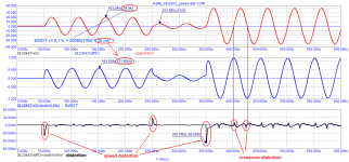
Crossover distortion is 2 ... 3 times higher than nonlinear distortion.
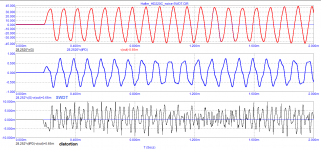
Measured the distortion of a signal with a frequency of 10 kHz.
Without changing anything, switched the signal to pseudo-noise of 10 kHz 1/3 octave (from a compact disc for checking the frequency response).
The SWDT amplitude remains the same, and the distortion level has doubled! (due to high-speed distortion).
According to the SWDT theory, the error level at a frequency of 20 kHz with an output voltage of 20 V should be no more than 20 mV, but in fact we have almost 600 mV! (30 dB more).
Attachments
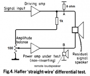
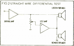
Here is a drawing from Hafler's original article Hi-Fi-News-1986-11_pp25-29
"The SWDT is elegantly simple, requiring no instruments. Its merits are obvious, but it is extremely difficult to apply because of its great sensitivity. A few minutes of phase shift, or some millibels of amplitude variation will show up as significant sound. This test shows most amplifiers to be audibly inaccurate. When a similar approach to amplifier testing was discussed in the past*,
the experimenters found relatively high levels of sound due to phase and amplitude variations. They did not consider these to be important, and they compensated the straight wire to minimize such variations. They made the assumption that phase variations were inaudible. This is disputable and controversial. We prefer to correct the amplifier to eliminate these aberrations rather than to eliminate them from the signal source. "
Hafler
Attachments
Last edited:
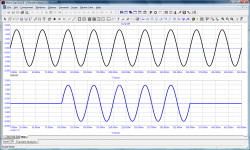
In the third of those images you have a switched 20kHz signal that's not band-limited, so the peaks you label as "speed distortion" are simply the result of the amplifier not having as much gain in the ultrasonic region as the audio band. This isn't non-linear distortion, its a frequency-response thing.According to the SWDT theory, the error level at a frequency of 20 kHz with an output voltage of 20 V should be no more than 20 mV, but in fact we have almost 600 mV! (30 dB more).
Discontinuities like this in a waveform carry a broad spectrum of high frequency energy, and don't represent standard audio signals which tail off rapidly above 20kHz.
If you use the input-output comparison method you have to ensure the test signal bandwidth is within the range for which the amp has flat phase and frequency response or you won't be measuring just distortion.
Note that these are discontinuities in the derivative of the signal, and are much less severe than steps in the signal itself (which will slew-rate limit), but they are still discontinuities with significant components upto MHz or so.
There is an issue that's seldom talked about, which is that many (mainly analog) synthesizers put out very wideband signals (square waves etc), and can be a hard for a live amp to handle gracefully without a 20kHz shelving LPF in the path.
Bob, you're wrong about the effect of the delay!
The SWDT test is the only correct test, you just need to apply it correctly, with the correct signals. All tests used today (THD, IMD, etc.) are at the lowest level of correlation with sound quality. This was known back in the early 50s of the last century, and to this day we are looking for lost car keys under the lantern at night, because it is brighter there. Here are the results of additional tests:
Crossover distortion is 2 ... 3 times higher than nonlinear distortion.
Measured the distortion of a signal with a frequency of 10 kHz.
Without changing anything, switched the signal to pseudo-noise of 10 kHz 1/3 octave (from a compact disc for checking the frequency response).
The SWDT amplitude remains the same, and the distortion level has doubled! (due to high-speed distortion).
According to the SWDT theory, the error level at a frequency of 20 kHz with an output voltage of 20 V should be no more than 20 mV, but in fact we have almost 600 mV! (30 dB more).
Crossover distortion IS nonlinear distortion.
Cheers,
Bob
You might want to consider the spectra of various chopped up waveforms, and how removing discontinities can drastically drop the amount of ultrasonic artifacts:
The last one has a raised cosine window applies to it (aka Hann window), removing the end discontinuities. There's far less spectral splatter (as its called in RF circles).
The last one has a raised cosine window applies to it (aka Hann window), removing the end discontinuities. There's far less spectral splatter (as its called in RF circles).
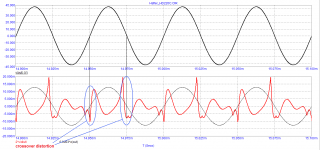
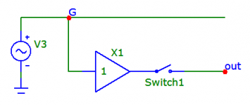
If someone does not understand my application of the Hafler SWDT test, then I hope they will understand the application of the Carver test.
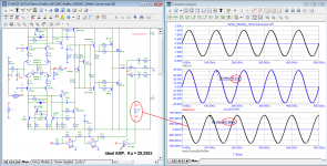
Carver's test consists in adjusting the parameters of the amplifier to the parameters of the reference. In this case, I used an ideal amplifier as a reference.
Amplifiers are "identical" by ear if the difference does not exceed -70 dB (3000 times).
With an output voltage of 42 V (peak), the voltage difference must not exceed 42000/3000 = 13 mV. In this case, the difference is 630 mV! that is, 630/13 = 48 times more.
So there is no need to talk about any reference amplification of this amplifier.
note. In previous tests, all test signals were passed through a low-pass filter with a cutoff frequency of 100 kHz, and the noise signal from the CD was processed by a 4th order Bessel filter with a cutoff frequency of 30 kHz.
Attachments
Last edited:
But the residual's just a tiny phase error! Come on! (its clearly in quadrature with the input).
If I get my sums right that represents a time error of 240ns, which is the time sound takes to travel 80µm
If I get my sums right that represents a time error of 240ns, which is the time sound takes to travel 80µm
Last edited:
Thermal Resistance of the Hafler DH220 Heat Sink
I estimate the Hafler DH220 heat sink (which should be about the same as the DH200) has a thermal resistance of roughly 0.535 °C/W. This is based on prorating from the diyAudio store Modushop chassis info. They provide thermal resistance ratings for each of their chassis. I have a Modushop Dissipante 3U-300. The thermal resistance rating for the 3U-300 heat sink is 0.41 °C/W.
Thermal resistance is proportional to the total surface area of the heat sink. The 3U-300 heat sink has 30 fins and a total surface area of ~3058 sq cm which includes the fin area, the area between the fins, and the back side of the heat sink. I included a 5% increase in the fin area due to the wavy surface. The DH220 heat sink has 16 fins and a total surface area of ~2346 sq cm which includes the fin area, the area between the fins, and the back side of the heat sink including the ears where the MOSFETS are mounted. So prorating on total surface area, the estimated thermal resistance for the DH220 heat sink is ~0.535 °C/W based on 0.41°C/W x 3058/2346.
The 0.535 °C/W seems reasonable based on it’s power output per the following. Using a max allowable heat sink temperature of say 60°C (keep in mind the DH220 thermal breakers are set at 70°C) and an ambient temp of 25°C (77°F) would result in a max heat dissipation for the DH220 heat sink of 65W [(60°C-25°C)/0.535°C/W]. The typical efficiency of MOSFETs is such that the heat generated is roughly half of the power output. Based on this, the power output that can be supported by the heat sink is 130W per channel which is slightly more than the rated power output for the Hafler DH220.
Would anyone know the thermal resistance of the Dh-200 heatsinks not some vague statement like I use a 300ma bias and they are fine but an actual rating like .57 degree per watt.
I estimate the Hafler DH220 heat sink (which should be about the same as the DH200) has a thermal resistance of roughly 0.535 °C/W. This is based on prorating from the diyAudio store Modushop chassis info. They provide thermal resistance ratings for each of their chassis. I have a Modushop Dissipante 3U-300. The thermal resistance rating for the 3U-300 heat sink is 0.41 °C/W.
Thermal resistance is proportional to the total surface area of the heat sink. The 3U-300 heat sink has 30 fins and a total surface area of ~3058 sq cm which includes the fin area, the area between the fins, and the back side of the heat sink. I included a 5% increase in the fin area due to the wavy surface. The DH220 heat sink has 16 fins and a total surface area of ~2346 sq cm which includes the fin area, the area between the fins, and the back side of the heat sink including the ears where the MOSFETS are mounted. So prorating on total surface area, the estimated thermal resistance for the DH220 heat sink is ~0.535 °C/W based on 0.41°C/W x 3058/2346.
The 0.535 °C/W seems reasonable based on it’s power output per the following. Using a max allowable heat sink temperature of say 60°C (keep in mind the DH220 thermal breakers are set at 70°C) and an ambient temp of 25°C (77°F) would result in a max heat dissipation for the DH220 heat sink of 65W [(60°C-25°C)/0.535°C/W]. The typical efficiency of MOSFETs is such that the heat generated is roughly half of the power output. Based on this, the power output that can be supported by the heat sink is 130W per channel which is slightly more than the rated power output for the Hafler DH220.
Last edited:
These are really nice insightful calculations and estimates.
Another approach (which I have not tried) is to attach a TO220 Centigrade temperature sensor like the LM34 to the heat sink to measure its temperature. Run the amplifier at idle for one hour and record its temperature to get a baseline at idle power. Calculate the idle power consumption at idle by measuring the rail current and multiplying it by the rail voltage. Measuring one rail should be enough if the power measurement is doubled.
Then run the amplifier at 100 watts into 8 ohms and do the same, measuring the higher rail current and reduced rail voltage to get total power consumption under 8 ohm load. Run the amplifier for 1 hour. Subtract the 100 W being delivered to the load resistor to get power delivered to the heat sink. Subtract the idle power measured above. Now you have delta temperature and delta power under actual operating conditions.
Cheers,
Bob
some of this discussion brings about a potentially interesting question.
does anybody have an XL-280 and 220C to perform the SWDT and compare results?
does anybody have an XL-280 and 220C to perform the SWDT and compare results?
Thanks Halfler Dh500 Fan. I was thinking about using the mosfets and heatsinks from a Dh220 for a slightly modified Pass M2 and from those figures it looks like it will indeed handle the heat.
Hi Mark,
Yes, that is painfully obvious. Of course you're not wrong.
-Chris
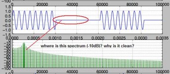
Chris, Mark, imagine this situation:
A million years ago, aliens flew to earth and left here an ideal generator that works to this day. All transient processes when it was turned on ended long ago. The generator does not suspect that I have connected a controlled switch to it and I want to form a burst. Therefore, that the first period of the burst, that the last period, that any other is absolutely the same, that is, ideal - without any distortion of the form. It seems that the spectrum of burst that you showed is sucked out of your finger. We see distortions of 2 ... 3% with the naked eye. You showed a spectrum in which only one second harmonic has a level of 30% (-10 dB). But I do not see these distortions either in the first period or in the last period of the burst ...
Attachments
As far as I know John Curl is a supporter of the high frequency of the first pole, as high as possible the upper frequency of the audio range, that is, much above 20 kHz. In this case, the phase of the loop gain in the entire audio range is zero. With single-pole correction and a low frequency of the first pole, the phase of the loop gain is close to 90 degrees. Here is what S. Ageev wrote about this in the article "Issues of designing amplifiers with common NFB", Radio 2003-04
(С.Агеев, «Вопросы проектирования усилителей с общей ООС», Радио 2003-04):
“When the phase angle of the loop gain is close to ± 90 °, ± 270 °, the amplitude nonlinearities of the original amplifier are almost completely converted into phase nonlinearities (ie, into parasitic phase modulation, albeit weakened by a factor of | bK | times). At the same time, parasitic amplitude modulation practically disappears, and the obtained results of intermodulation distortion measurements can be 20 ... 30 dB more optimistic than the spectrum analyzer actually shows (and hearing in the case of Amplifiers). Unfortunately, this is exactly the case with most op amps and many Amplifiers. "
his own statement on one of the forums about vector distortions that depend on the signal transmission delay (time Propagation Delay):
“If the vector error is very small (less than 0.01%), there is no statistically discernible effect of the amplifier. Just neutral, detailed, but without traces of harshness, and, what is important, reproduced regardless of the topology and amplifier design. That is, amplifiers of different circuitry and ideology, which fit into a real signal of 0.01%, are almost impossible to distinguish, as well as to notice any defects that could reliably be attributed to the amplifier."
- Home
- Amplifiers
- Solid State
- Hafler DH-200/220 Mods