@ jbell
I didn't see GM's post about DCR until after i had posted my thoughts about it. I had composed my post offline some time before logging in here, and GM had posted.
@ GM
Sorry if it "appeared" i stole your idea, i can Assure you i did Not.
*
@ tb46
Hi, thanks, yeah i thought the # looked a bit wierd, but i just grabbed the PDF # i received & posted it ! On revisiting the patent www just now, i found unless i included a / as in 12/877950 it didn't list it ! I found the ones i posted by searching by name first 😉
It looks like a reversion chamber, like the ones used on race motorcycle exhausts. It is used to produce a back-wave 180deg out of phase of frequencies that you want to kill in a Transfer line (or exhaust, same thing really). They can also be used to create back-pressure packing (120-160deg out dependent on freq.) i.e. wave scavenging.
ref: http://www.google.com/url?sa=t&sour...ubHTCQ&usg=AFQjCNGBOJixIKH3qtyZElcDav6DtzhDsQ
ref: http://www.google.com/url?sa=t&sour...ubHTCQ&usg=AFQjCNGBOJixIKH3qtyZElcDav6DtzhDsQ
Last edited:
I think GM nailed it -- double bass reflex. No TL even involved.... (unless you consider the narrowing of the long port as a TL....)
From the 'fresh' patent..... page 1. ...
That drawing is perfectly modelable in AkAbak, given some dimensions.
It's more like a standard reflex with an additional resonator rather than a DCR in the accepted sense of the term.
@ GM
Sorry if it "appeared" i stole your idea, i can Assure you i did Not.
No problemo, I've been 'caught out' the same way many times........
GM
I think GM nailed it -- double bass reflex. No TL even involved.... (unless you consider the narrowing of the long port as a TL....)
FWIW, the earliest version of this type loading [less the resonant chamber] were called acoustic labyrinths back in the '30s. Never seen it in a patent, but Harry Olson noted on a sketch that he needed to work up just such a chamber to add to his early '30s BLH studio monitor. For sure, this measurement of a later one seems almost be too good to be true without one since the Hartsfield was bigger and no slouch in the bass:
GM
Attachments
From the opening of Mr. Clements response to my e-mail:
He further says the speakers will be @ CEDIA this year (soon, in INDY) and the Phoenix, AZ, USA area where he is based.Hi Ed,
and thanks for the heads up. Not sure how or where to sign up, but would gladly join in the conversations. Certainly, I am glad to take emails here at the office as well.
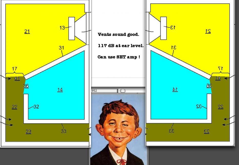
The 117dB they mention is that taken near field at the vent, not at the usual one meter. The overall sensitivity remains that of the bass driver itself rated at 1m/2.83v input.
However, the output at the vent is significantly higher than that observed from typical vented systems due to the pressure created from the inverse horn section of the enclosure. As mentioned at the competition, it is not just the extended low bass achieved in doing this it is the added dynamic range to the lower frequencies that sets H-PAS technology apart.
I could be completely off track, but my take on the H-PAS patent:
It seems to be a bass reflex design, constructed in the form of a short tapered transmission line (however, too short for the line length to have significant effect). Constructed as such, the acoustic impedance variations of the bass reflex enclosure can be flattened with the use of a coupled (closed) resonant chamber (instead of stuffing).
I believe I've seen a coupled-resonant-chamber used to flatten the acoustic impedance in a closed box/transmission-line, but I've never seen it applied to an open (ported) one [If someone has, please link]. (The topology seem more akin to dual-chamber-reflex with a closed secondary chamber, than it does to double-bass-reflex, IMHO.)
As far as I can tell, there is enough originality to warrant a patent.
If I'm off the rails, I welcome being put back on track.
From the opening of Mr. Clements response to my e-mail:
Quote:
Hi Ed,
and thanks for the heads up. Not sure how or where to sign up, but would gladly join in the conversations. Certainly, I am glad to take emails here at the office as well.
The 117dB they mention is that taken near field at the vent, not at the usual one meter. The overall sensitivity remains that of the bass driver itself rated at 1m/2.83v input.
However, the output at the vent is significantly higher than that observed from typical vented systems due to the pressure created from the inverse horn section of the enclosure. As mentioned at the competition, it is not just the extended low bass achieved in doing this it is the added dynamic range to the lower frequencies that sets H-PAS technology apart.
He further says the speakers will be @ CEDIA this year (soon, in INDY) and the Phoenix, AZ, USA area where he is based.
Ed,
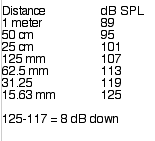
Mr. Clement's response made me think of the inverse square law.
I calculated the output of a vent “taken near field at the vent” compared to a speaker with a sensitivity of 89 dB one watt one meter, using the 6 dB increase per halving of distance the inverse square law predicts, the figures below.
At 15.6 mm (about 5/8 inch ) from the vent, one could expect about 125 dB from a speaker with flat response down to the vent frequency, 117 dB would be about 8 dB down in response with a 89 dB output. If one assumes the speaker puts out half the level, and the vent the other half down low, reduce the above vent figures by 3 dB.
To check my figures, having a “ typical vented system “ a Tannoy PBM 6.5 (a small two way speaker) and a Radio Shack SPL meter handy, I played pink noise (LP at 24 dB per octave above 160 Hz) into one speaker, set the level to 89 dB SPL at one meter, indoors.
Moving the meter to 5/8 inch from the vent SPL was 118 dBC, with the meter’s microphone flush with the vent, SPL was 120 dBC.
The “ typical vented system" read 1 to 3 dB higher “at the vent” than the H-PAS technology.
Of course, allowing for the fact that “C” weighting reads a bit less than flat below 100 Hz, the Tannoy’s vent output may may be a bit louder yet.
Hoffman’s Iron law still seems to be unbroken 😉.
Art Welter
Attachments
Last edited:
I think GM nailed it -- double bass reflex. No TL even involved.... (unless you consider the narrowing of the long port as a TL....)
From the 'fresh' patent..... page 1.
I think we need the ohm of the driver used... The language is suspicious on the "2.83 volt, what is normally considered 1 watt...."
Sounds like marketing speak when using a 2ohm driver.
A year or two ago I published a bunch of Akabak models of enclosures with multiple woofers, and one thing that I noticed is that you can get away with drivers that have a lower impedance than normal because the impedance troughs are staggered a bit.
For instance, in a conventional bass reflex speaker, if you have two woofers with an impedance of six ohms and they're wired in parallel, the impedance trough will be about three ohms because the helmholtz resonance is the same for both woofers.
But in a transmission line or a horn with multiple woofers the impedance trough will be slightly higher because the quarter wave resonance is different for each woofer. This is because the length of the line is a bit different for each one.
The effect isn't huge by any means, but it might enable a manufacturer to get away with six ohm drivers instead of eight ohm drivers, and still 'pull off' a four ohm load in parallel.
Of course, the effect will become quite complex in a line like this, since that additional chamber will change the impedance curve.
I really need to find an hour or two to make an Akabak model of this.
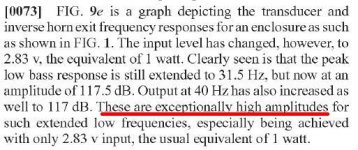
To check my figures, having a “ typical vented system “ a Tannoy PBM 6.5 (a small two way speaker) and a Radio Shack SPL meter handy, I played pink noise (LP at 24 dB per octave above 160 Hz) into one speaker, set the level to 89 dB SPL at one meter, indoors.....
Hoffman’s Iron law still seems to be unbroken 😉.
Art Welter
THANKS ART !!!
I'm betting the 117db was eye opening to the patent guys and probably played a roll in the process....
Measured at the vent.... I knew my BS-O-Meter was pegging 10. At least when I assumed 1 meter.... If you read carefully, it does kinda say 'at the vent.' I just missed it.
from the patent...
Attachments
Last edited:
117dB etc
@ GM
There a quite a few patents based on labyrinth type enclosures. Here's one from 1936 !
@ Ed LaFontaine
Thanks for contacting PC & sharing that info 🙂
My thoughts exactly, but the TL type taper is there !
@ weltersys
Yes those Extremely high SPL levels seemed too good to be true, now we know why 😀
Good point 😉
Yeah me too. Stating measurements at the vent like that, is very misleading IMO.
@ GM
There a quite a few patents based on labyrinth type enclosures. Here's one from 1936 !
Acoustic Labyrinth loudspeaker enclosure patented by Olney http:/documents.jordan-usa.com/Famous-Articles/Augspurger-Loudspeakers-on-Damped-Pipes.pdf
@ Ed LaFontaine
Thanks for contacting PC & sharing that info 🙂
Originally Posted by thune
(however, too short for the line length to have significant effect).
My thoughts exactly, but the TL type taper is there !
@ weltersys
Yes those Extremely high SPL levels seemed too good to be true, now we know why 😀
Originally Posted Patrick Bateman
This is because the length of the line is a bit different for each one.
Good point 😉
Originally Posted jbell
At least when I assumed 1 meter.
Yeah me too. Stating measurements at the vent like that, is very misleading IMO.
@ GM
There a quite a few patents based on labyrinth type enclosures. Here's one from 1936 !
Ed LaFontaine
Thanks for contacting PC & sharing that info 🙂
My thoughts exactly, but the TL type taper is there !
weltersys
Yes those Extremely high SPL levels seemed too good to be true, now we know why 😀
Good point 😉
Yeah me too. Stating measurements at the vent like that, is very misleading IMO.
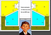
Misleading?
Nahh.
Attachments
I've read the patent a couple times now, and I have a better understanding of what is claimed:
1. 5hz greater extension over a standard ported cabinet (37hz vs 42hz)
2. Two db greater output at 40hz vs standard box. (at the vent, due to higher vent velocity)
3. Really great distortion numbers measured at 0.5v... (yea half a volt, 0.031 watts)
Very believable, and obviously patentable -- but somehow I don't think anyone is going to try to rip off this patent... In my view, it's "safe."
Gentlemen,
Thank you for your scrutiny. I didn't feel like my "BS 'o meter" needed to come out of its holster while trying to gain any insight that may be available from Mr. Clements. He has been cordial and engaging...
Thank you for your scrutiny. I didn't feel like my "BS 'o meter" needed to come out of its holster while trying to gain any insight that may be available from Mr. Clements. He has been cordial and engaging...
Gentlemen,
Thank you for your scrutiny. I didn't feel like my "BS 'o meter" needed to come out of its holster while trying to gain any insight that may be available from Mr. Clements. He has been cordial and engaging...
apology for any offense -- none was intended, to you or mr. clements.
The measurements involved in this patent are far from 'typical' and are not explained well. 117db in 2pi space at one watt is not possible at one meter -- and my surprise at that measurement is what I was trying to communicate.
No one that I'm aware of measures a speaker 'near field at the vent' which means that the measurement is not repeatable because we don't know 'exactly' where the measurement mic was placed, and fractions of an inch make a big difference, as art pointed out. 2pi at one watt and one meter distance is what is assumed for any standardized measurement, and that is exactly what I assumed. Mine was not the first post that assumed there was something wrong or misleading with the measurements in the patent, as post #14 first called it out.
Please pass along to mr. clements the appreciation of knowing the measurements were 'near field at the vent' as that was the big missing piece of information.
All is good. No apology needed.
I "think" Phil Clements has a customer in Atlantic Technology that wants to present themselves to the market in the best way possible. They certainly have a lot riding on booth space at CEDIA and other marketing...such is the nature of the beast.
I sure would like to see Martin's tailored worksheets for this if only to gain insight to any effects the "bass trap" has and how we might use that to advantage. I "think" the business side of things will keep that tied up. Exposure of what is really, really happening would likely undermine the way AT wants the general consumer to "see" them.
We aren't "general consumers" here, are we?
 lol
lol
I "think" Phil Clements has a customer in Atlantic Technology that wants to present themselves to the market in the best way possible. They certainly have a lot riding on booth space at CEDIA and other marketing...such is the nature of the beast.
I sure would like to see Martin's tailored worksheets for this if only to gain insight to any effects the "bass trap" has and how we might use that to advantage. I "think" the business side of things will keep that tied up. Exposure of what is really, really happening would likely undermine the way AT wants the general consumer to "see" them.
We aren't "general consumers" here, are we?
Last edited:
Neat design tricks etc
On re-reading the Augspurger-Loudspeakers-on-Damped-Pipes.pdf that i linked to earlier, amongst lots of other interesting data etc in there, are these fascinating findings, in the screenie below.
Several of those novel ideas "seem" to be included in the H-PAS technology ! All good stuff & i wish i'd read it years ago 🙁
H-PAS can obviously be modelled, as MJK has provided PC with a custom version of his TL spreadsheet. So i expect "someone" must also be able to do it with for eg Akabak etc, as has been mentioned previously. Who will be the first i wonder 😉
I wish Phil Clements et al, all the best, & especially after waiting over 30 years ! Dreams can come true, sometimes, eventually. So there is hope for the rest of us too 😉
Attachments

Hi Y'all,
This test report may be of interest: Test Report: Atlantic Technology AT-1 H-PAS Speakers | Sound and Vision Magazine
Regards,
This test report may be of interest: Test Report: Atlantic Technology AT-1 H-PAS Speakers | Sound and Vision Magazine
Regards,
Exposure of what is really, really happening would likely undermine the way AT wants the general consumer to "see" them.
Yea, I kinda shook my head once I completely understood what the patent measurements were saying.
A 10% larger box, that was making 1.5db more bass (that they rounded up to almost 2db) AT THE VENT only that also dropped the F3 by 5hz. (that they rounded up to almost half an octave more extension)
Due to the increased velocity by the reducing area of the vent -- "At the vent" measurements should obviously read artificially higher, relative to the 1 meter measurements. (a really undersized port would have skyrocketed the "at the vent" spl numbers)
All in all, I don't "think" there is over a full db more total output from a 1 meter measurement because the port isn't 100% of the output. (logic says it must be less than 1.5db)
This looks to be a good way to get an extra 5hz and possibly a db extra from a 5 1/2" driver in a 10% larger box and to say that it's patented technology.
But then I guess marketing is marketing....
- Status
- Not open for further replies.
- Home
- Loudspeakers
- Subwoofers
- H-PAS patent pending to Atlantic Technology