Connect a ceramic capacitor starting at 30pf between the gate of only one mosfet (N type) and the positive rails. if there is a good effect but still oscillating increase size to max 100pf or do the same with p-type with negative rails. sometime trial it with 2nd 3th or 4th mosfet.
It did the trick with many lateral transistor projects.
It did the trick with many lateral transistor projects.
IIRC Hitachi J50 / K135 were originally fitted.What are the MOSFET parts?
You can see videos on YT where there are tens of these amps at raves and concerts in the late '80s and early '90s. I can't believe they would have been used in such quantity if there were a blatant oscillation by design.
Unless there are details that I'm missing, the topology appears to be a variant on the Hitachi L-MOSFET apps data one, used in the HMA-7500 and Maplin amps. I dug a couple of mine out a couple of weeks back and found that @ 10W output, distortion never went above -80dBV. Link here: https://www.diyaudio.com/community/threads/maplin-mosfet-amplifier-ga28f-construction-thread.257488/
(this was with plenty of bias BTW - it's a basic design that needs it if you want low THD into loads)
The Hitachi design is notoriously rugged. They can oscillate if the input is left open, whereupon the Zobel will get hot. It's common to see the amps for sale with blackened Zobels.
The toplogy can be a little twitchy, but there's no way it could be descibed as inherently unstable.
edit - do check the HMA-7500 schematic out. It retains the I/P offset control omitted in the Maplin version.
They are the famous Hitachi Lateral MOSFETs, developed by Hitachi. As I wrote before, the topology looks almost identical to that used in the HMA-7500. I am not seeing a Zobel (maybe I am missing it...?), which is usually shown on all Hitachi L-FET designs.
Lateral fets would explain why the bias is fairly simple, and as they were not particularly fast (1MHz or so if I recall correctly) then there should not be much problem of stability. So, it would suggest that one or more of the devices is malfunctioning.
@thermionic - the circuit posted earlier showed a peculiar network of C-L//R-C which does not seem optimum. My recommendation was to put a resistor in series with the first C and remove the second, but L//R -C should work too. Not an approach I have used, but Cherry did.
@thermionic - the circuit posted earlier showed a peculiar network of C-L//R-C which does not seem optimum. My recommendation was to put a resistor in series with the first C and remove the second, but L//R -C should work too. Not an approach I have used, but Cherry did.
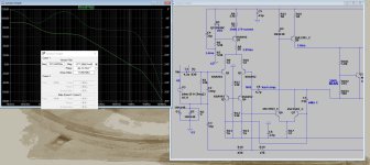
valgamaa had it. get a 33-47pf silver mica for the Q5 (miller cap) and 5-10p for C4. This amp is one of my input stages for "slewmaster".
No one simulated this ? I have even built it (slewmaster) , forgot where the inspiration came from?? Can't believe they were relying on the VAS BJT's Cob
and then using an oversized lead compensation cap to cover up a bad design. Ceramic caps ! Blasphemy !
You end up with a typical 735Khz unity gain circuit with 93db phase margin - quite stable. 10pF (miller cap) in my simulation resulted in 1.6MHz oscillation.
OS
Attachments
Would you post a drawing that shows the entire amplifier? At first I was alarmed that I couldn't spot a DC connection of SG (pin 4 at board edge) to "ground." Eventually I found another SG path that led to the power supply. Is this connection a wire connection across the chassis?
I share suspicion about the lack of a proper Zobel network.
How do we know if the oscillation is due to "global feedback" vs. a local inter-stage oscillation? As an experiment, I suggest installing a short across R10. That should establish working bias, but let the amp run with full open-loop gain; I believe global oscillation will be precluded and any remaining oscillation should be localized instability.
From your description, it sounds like the bottom half of the output stage is unstable. Try increasing the gate stopper resistor values on this half and see what effect it has. i.e. R68, R69, R70, R80.
If there are connectors involved in the connection of the output transistors to the main PCB, make sure they are all good. Also make sure the output transistor screws are not loose.
Oh yeah, from the pictures, it looks like the output transistors are in sockets. That might be problematic. You could try removing the bolts, levering them up, pushing them back down a few times to improve contact.
If the Laterals really are in sockets, then that alone strikes me as an oscillation risk... But it does make it easy to test them. Assuming that you have a basic transistor tester, I would take each one out and test it. A simple unit such as the Peak Electronics unit will do this - I've used it for laterals before.
Thank you all for your suggestions!
Yes the FET's are in sockets. There is no isolation between the FET's case and heatsink, so there are two large heatsinks, each mounted with 4-4 MOSFET pairs, and since the case is the SOURCE terminal, the heatsink is directly the speaker output of the two channels. The heatsinks are rubber-bonded to the case in parallel, I suspect there is at least 100pF of capacitance between the two channel outputs. Perhaps that is why both channels produced almost the same phenomenon, at almost the same frequency and amplitude. BUT, after the changes described in https://www.diyaudio.com/community/threads/h-h-v800-mos-fet-amp-oscillating.397284/post-7305601 post, the oscillation on the channel in question was greatly reduced, but regardless, the other channel (the one in its original, untouched state) produced the same oscillation, so I guess it could be a case of aging of the FETs, since both channels, independently of each other, produced the same thing.
These are 40-year-old parts, so who knows. Another thing is that the area between the FET case and the heatsink is filled with silicone-like material due to heat transfer, the MOSFET's GATE and DRAIN terminals are "sitting" in the grease. I wonder if this grease-like material might become a bit conductive after 40 years? Lots of possibilities 🙂
Do you have a tester? Like this: https://www.peakelec.co.uk/acatalog/dca55-atlas-dca-semiconductor-analyser.html
My advice is to go through the FETs one by one, making sure that they are ok. I don't see the 40-year age being a problem. Driving sub stacks at festivals for 4 decades is likely to have taken its toll, as it would do on any amp. If the FETs test ok, I am sure they will be ok. I would be most concerned about the mounting, and ensuring that the insulation hasn't broken down.
My advice is to go through the FETs one by one, making sure that they are ok. I don't see the 40-year age being a problem. Driving sub stacks at festivals for 4 decades is likely to have taken its toll, as it would do on any amp. If the FETs test ok, I am sure they will be ok. I would be most concerned about the mounting, and ensuring that the insulation hasn't broken down.
Unfortunately, I don't have one of those testers. Actually, the device works, but the oscillation at the output -visible only with an oscilloscope- was disturbing. There is no isolation between the MOSFETs case and the heatsink, the heatsink is galvanically equal to the output.
...and the schematic of the V800 (This seems to be a slightly earlier release, the amplifier part of the actual unit looks more like the M900, but of course the I/O connectors and the LED level meters on the V800 wiring diagram are shown in reality)

Hi mickeyratt,
Thanks very much for the big view on the schematics.
IMHO, the V800 shown in post 49 is closer to a reasonable design. Am I correct that your amp doesn't have an R20 site in series with C7, i.e. no provision for a Zobel network?
The frequent revisions of the amp's compensation suggest the manufacturer struggled with stabilizing the amp. I can't reconcile the argument that the proliferation of these amps proves they must have been reliable, but the frequent design tweaks focused on compensation seem telling.
The presence of C4 shunting R11 suggests the designer wanted to extend the closed loop bandwidth, but many other design details conspire to restrict the bandwidth: eg. relatively large gate resistors (R65-R68, etc.), C6, C22, C7, C18, C11, C10, C35, cap at Q10 b,e. I get the impression that many of these components are unsuccessful attempts to suppress oscillation.
Simply stated, the open loop amp should be designed for maximum bandwidth, probably constrained by the gate resistors needed to prevent self oscillation of the MOSFETs. Typically, then a single (Miller) capacitor is used to lower bandwidth enough that unavoidable phase shift from the output stage doesn't intrude enough to provoke oscillation. More later.
- Home
- Amplifiers
- Solid State
- H||H V800 MOSFET Amp oscillating