Really long story....in short
Amp came in with blown up capacitors in the class D output filtering, the ones 1uf 400v between the output terminals and ground. 10ohm 5W resistor was in bad condition too.
Replaced those.
Amp now has DC offset of approximately 20v which can NOT be fixed by the trim pot, it can fix only 1-2-3volts of difference not more. It plays, no protect, class D switching is present, but as You can imagine having 20v DC on a speaker = not good.
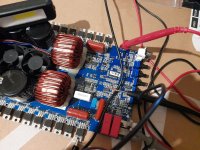
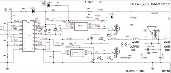
Seems like one of the amplifiers, in RED (it is full bridge class D) works with 20v-21v LESS than the other one in BLUE. These are the only differences I found between both amps driver IC's, pictures are attached. What I understand....when having a 150v rail, there should be aprox. 75v at each output terminal....now I do have 85v at the one and 65v at the other....not good. Connecting a load does not change the DC offset. How to fix this disbalance ?
One of the amps in this full bridge, the one in RED, with less voltage present, the low side outputs are warming up. 1 minutes of idle = 60-70degrees, high side stays normal/cool.
So i've put my effort in this RED "amp" where the heating up is happening, I do use the other one BLUE "amp" as a reference as it's not heating up.
What i've replaced so far - IRS20957s, both buffers (the 6 pin drivers), all of the 15v zeners, all of the MUR120 diodes, all the resistors near the driver/buffer, IC, zeners, all of output transistors. Parts are from reputable source. So even after changing all of this, there is NO single difference. It is exactly behaving the way it was before doing any work at it.
Any ideas ?
I will attached some of my draft measures.
Amp came in with blown up capacitors in the class D output filtering, the ones 1uf 400v between the output terminals and ground. 10ohm 5W resistor was in bad condition too.
Replaced those.
Amp now has DC offset of approximately 20v which can NOT be fixed by the trim pot, it can fix only 1-2-3volts of difference not more. It plays, no protect, class D switching is present, but as You can imagine having 20v DC on a speaker = not good.
Seems like one of the amplifiers, in RED (it is full bridge class D) works with 20v-21v LESS than the other one in BLUE. These are the only differences I found between both amps driver IC's, pictures are attached. What I understand....when having a 150v rail, there should be aprox. 75v at each output terminal....now I do have 85v at the one and 65v at the other....not good. Connecting a load does not change the DC offset. How to fix this disbalance ?
One of the amps in this full bridge, the one in RED, with less voltage present, the low side outputs are warming up. 1 minutes of idle = 60-70degrees, high side stays normal/cool.
So i've put my effort in this RED "amp" where the heating up is happening, I do use the other one BLUE "amp" as a reference as it's not heating up.
What i've replaced so far - IRS20957s, both buffers (the 6 pin drivers), all of the 15v zeners, all of the MUR120 diodes, all the resistors near the driver/buffer, IC, zeners, all of output transistors. Parts are from reputable source. So even after changing all of this, there is NO single difference. It is exactly behaving the way it was before doing any work at it.
Any ideas ?
I will attached some of my draft measures.
Attachments
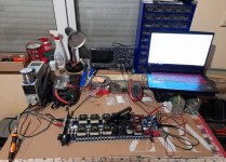
For some reason, seeing that computer where it was brought Salvador Dalí to mind.
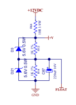
Is the 'float' voltage precisely divided across the two 1k ohm resistors? Very nearly precisely 1/2 of the 15v regulator output?
Is the 'float' voltage precisely divided across the two 1k ohm resistors? Very nearly precisely 1/2 of the 15v regulator output?
Check yuour PM I have given you a whole lot of information as to what to check for. Information that I cannot post for all to see.
Which ones 1k ? The ones in the feedback circuit ? Fb1 and Fb2 connecting to the error/comparator op amp ?For some reason, seeing that computer where it was brought Salvador Dalí to mind.
Is the 'float' voltage precisely divided across the two 1k ohm resistors? Very nearly precisely 1/2 of the 15v regulator output?
If you can get help from someone who knows these amps, they will be more useful than I am.
The 'float' network is the bias point for the audio circuit. There have been many times when one of the two 1k resistors in the voltage divider go out of tolerance and that can cause various problems so it's something I recommend checking. The networks vary. Some have the diodes, some are just a series of 3 resistors coming off of the 12/15v regulated supply. The attached image is just a generic example.
The 'float' network is the bias point for the audio circuit. There have been many times when one of the two 1k resistors in the voltage divider go out of tolerance and that can cause various problems so it's something I recommend checking. The networks vary. Some have the diodes, some are just a series of 3 resistors coming off of the 12/15v regulated supply. The attached image is just a generic example.
Attachments
Fixed it.
I got frustrated and changed every diode, resistor, capacitor and element in the Feedback section.
Works fine now.
I bet one of the those elements got out of tolerance once voltage is applied or something like this (measuring it while not turned did not show up anything on the MM.)
I got frustrated and changed every diode, resistor, capacitor and element in the Feedback section.
Works fine now.
I bet one of the those elements got out of tolerance once voltage is applied or something like this (measuring it while not turned did not show up anything on the MM.)