what i like about gyrator, is the predictability of tube bias point. you adjust the desired plate U, and adjust current by tube Rc. always repeatable, no matter power supply. even more important with low Ua dht battery tubes.....150v max or so. no problem, even with 400v poweramp another bonus is low Z output.
with ccs you have more variables-unknowns. you adjust desired Ia on ccs. when adjusting Rk, the Ua moves too. (strongly) if you tune tube to cutoff, driver tube gets full Ua, which may be problem for vintage bulbs. not all, if any ccs has low Z output. that hurts most.
in AC mode, driver tube seems same high Z, there is not much difference.
Well; the problem of loading vacuum triodes is, they need current and voltage to operate. The higher current we want, the lower should be load resistance. But the lower is load resistance, the more the tube distorts! But increasing load resistance we have to increase the voltage that powers the stage, until the tube gets damaged.
CCS is a Constant Current Source (or a sink). It maintains current as needed, but has huge dynamic resistance. It is all good, except the working point of the tube highly depends on it's geometry and emission. That means, when we swap the tube, or it ages, or filament voltage floats, anode voltage differs as well. What I did, I added a servo to CCS, turning it into a gyrator.
Gyrator is a thingy that transforms impedance. In this particular case, it transforms impedance of a capacitor into an inductive load, i.e., as the result the tube is loaded as if on a very high inductance of very good quality, so the tube adds as less as it can distortions, i.e works always in ideal conditions, no matter if we swap tubes, it ages, or filament voltage changes.
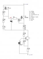
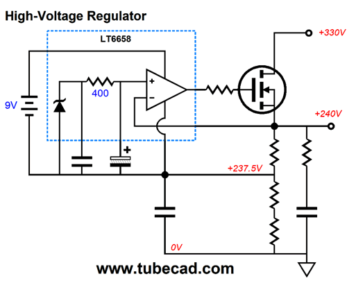
I add to this thread to not open a new one, in a gyrator like the one in the diagram, the capacitor having no reference to ground, should not receive all the input voltage at its ends, is this correct? How is it possible to estimate the capacitor voltage considering a 300v input supply?
Attachments
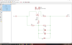
I add to this thread to not open a new one, in a gyrator like the one in the diagram, the capacitor having no reference to ground, should not receive all the input voltage at its ends, is this correct? How is it possible to estimate the capacitor voltage considering a 300v input supply?
Taking the voltage between the circuit terminals as Vt, the capacitor voltage is then obviously:-
Vcap = vt x R2 / (R1 + R2), provided the zener does not turn on.
But the circuit is not a gyrator (a two-port device/circuit that presents at one port the reciprocal of the impedance at the other port), it is merely an AC constant current load that has a resistance to DC equal to:-
Rtot = R3 x (R1 + R2)/R2.
For frequencies below a cut off frequency set by C and R1//R2, the circuit has a resistance Rt, and for frequencies above, it is a constant current load (rt dependent on the FET.
A gyrator would convert a pure capacitance into a pure inductance at all frequencies of interest, or nearly so, and show no transition of impedance at one frequency.
Keit;
the definition of a gyrator is conversion of the impedance. Not necessary into an inductance, and not necessary into an ideal clean theoretical inductance.
the definition of a gyrator is conversion of the impedance. Not necessary into an inductance, and not necessary into an ideal clean theoretical inductance.
True (well, partly - a gyrator must have 2 ports as I said), and not in conflict with what I said.
An ideal gyrator converts an ideal capacitance into an ideal inductance, converts and ideal inductance into an ideal capacitance, converts an ideal resistance in series with and inductance into an ideal resistance in parallel with an ideal inductance etc, etc.
But NOTHING is perfect in this universe, and certainly not resistors, capacitors, inductors, and gyrators.
However, unlike practical inductors, ordinary resistors and capacitors are often very nearly perfect at common frequencies, and it is easy to make a very good gyrator. Thus gyrators have often been used when a very nearly ideal inductor is needed, or a very compact inductor is needed.
> How is it possible to estimate the capacitor voltage
What Wavebourn said; but also: the cap is gate to source. i.e. across the gate oxide. If oxide voltage is much over 20V, POOF the gate vanishes and the MOSFET is dead.
Oxide may actually take 30V or 40V depending on processing. However gates never need even 10V. The Zener protects against accidents (including static discharge) and is often 9V or 12V one way, 0.6V the other way. The normal operating gate voltage is like 4V. So a 16V cap is ample, and protected by the Zener, and even if not it is like the expensive delicate MOSFET will blow before the cheap robust cap.
> However gates never need even 10V. The Zener protects against accidents (including static discharge) and is often 9V or 12V one way, 0.6V the other way. The normal operating gate voltage is like 4V. So a 16V cap is ample, and protected by the Zener, and even if not it is like the expensive delicate MOSFET will blow before the cheap robust cap.
No. The initial turn on voltage for the IRF840 is 4.0 V. To guarantee it is fully turned on requires 10V. (See IR or Vishay/Siliconix datasheet.). In any given circuit, the "normal" gate-source voltage will be somewhere in between, usually quite a bit more than 4.0 V.
Also, there needs to be a volt drop across the source resistor, R3. For effective circuit operation as a const current source, and to get the desired current within a tolerance, this needs to be a little greater than the gate-source voltage, say 10 to 20 V.
Therefore the operating voltage across the capacitor needs to be around 16 to 25V. To be effective in protecting the MOSFET, the Zener needs to be return direct to the source, not the bottom end of the capacitor. This is because it can then be a 10V Zener and not a 27V Zener, and its effectiveness depends on being connected as directly on the MOSFET as possible.
R4 is necessary to provide a stopper effect to ensure the MOSFET doesn't oscillate. However it introduces another failure mode. If the circuit positive terminal (X1) is connected direct to HT, and the other terminal (X2) is suddenly shorted to ground (eg by a slip of a meter probe, or tube flashover), the MOSFET internal capacitance transfers some of the fast rise time voltage to the gate. If the short is fast enough, the time constant of the internal capacitance and R4 may be sufficient to destroy the gate. Depending on circuit constants, this may or may not be a problem. If calculation shows that it might be, an RF choke in series with X-2 is a cure. Or use a suitably rated bipolar instead of a MOSFET.
Last edited:
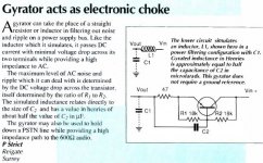
Is this calculation valid?
Asume there's 10mA circuit current, of which 1mA is running through R1+R2.
GS is at 8V
over R3 is 16V (@9mA -> 1778R)
over R2 is 24V (@1mA -> 24000R)
R1 allows for 8V at G, R1= 8/0.001= 8000R
value of the gate stopper should be examined, say 100R.
Asume there's 10mA circuit current, of which 1mA is running through R1+R2.
GS is at 8V
over R3 is 16V (@9mA -> 1778R)
over R2 is 24V (@1mA -> 24000R)
R1 allows for 8V at G, R1= 8/0.001= 8000R
value of the gate stopper should be examined, say 100R.
Attachments
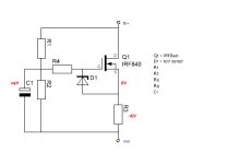
Disco: Not quite, unless you want the circuit to behave as a resistance to DC of 32 V / 10 mA ie 3200 ohm.
If (B+ - out) = 24V, no volt drop is allowable across R1. Let's assume (B+ - out) is a design centre of 100V. Then R1 = (100 - 24) / 0.001, ie 76 kohm.
Note that if (B+ - out) rises to 200V, the bias current through R1 and the current through the MOSFET double to a total of 20mA.
As I said before, this circuit behaves as a resistor at DC (in this case 10 kohm), but a constant current source for AC.
As I said before, this circuit behaves as a resistor at DC (in this case 10 kohm), but a constant current source for AC.
For a CCS the dependence of PS voltage is unwanted. So, in comes a seperate bias loop. The first take loads the anode to ground over R2, again not ideal. The second take is self containing with soft power on over C1 being loaded by the bias string.
Still, what we need is high impedance over the complete AF band. Would this third take do it without exhausting too much CO2? Silly value for C2 though to arrive at 250H...
Perhaps the combined amplification of a Darlington pair could be useful...
Attachments
Disco: I think you are over-engineering. And if you think putting an inductance (even a poor one) in series with a const current circuit (even a poor one) you make you have another think. A well designed CC circuit has an extremely high impedance, making a series inductance quite unnecessary.
I cannot speculate on how much effort needs to be put into this, because I don't know the application. Possibly the application is spelt out earlier in this thread, but I'm too lazy to go search for it.
Mr Strict can call his circuit a gyrator if he wants - England is a free country. I wouldn't call it a gyrator. For a start it is not a (bidirectional) two-port. And it would be a poor version of the MOSFET circuit presented earlier - that is it would behave as a resistor below a certain frequency, and an approximate const current circuit above that frequency, - but (unlike the MOSFET circuit) with that frequency somewhat less determinate, and the current in CC mode not as constant.
Perhaps the combined amplification of a Darlington pair could be useful...
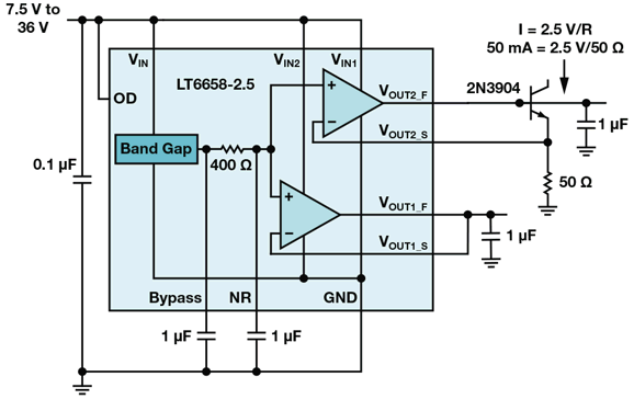
or how about replacing the entire left side (LND150 current source and the voltage divider R1 R2 P1) with a precision voltage reference? You gain a sense resistor (R3) and an auto bias servo.
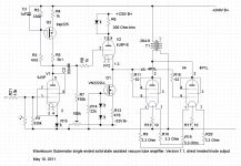
Pentode Super-Triode
Last edited:
Wow, has it really been that long? I've been using your 3 transistor version since then. An incredibly useful circuit ! ! ! Did I say that it sounds good? No, I'd better not, IIRC, you think that such circuits don't "have sound". Regardless, It's great and Thanks for sharing it ! ! !
Yes, ant it was what started the "Gyrator Fashion" on diyaudio forum. 🙂

It was totally adequate for a microphone preamp. A single BJT, nothing more. 470k R3 did not hurt, since the next stage has a grid leak resistor.
It was totally adequate for a microphone preamp. A single BJT, nothing more. 470k R3 did not hurt, since the next stage has a grid leak resistor.
The circuit posted by Wavebourn in #78 is quite a smart circuit, because Q1 is isolated from high voltage and thus can be a high gain type. That means R3 can be a high value. The circuit would cost a lot less than a MOSFET version. Yet it will be a heck of a lot more reliable. Its a better good const curr circuit, also because the output resistance of Q2 is unimportant, due to a const feed from Q1.
But whether it, or nay other CCS, will produce a better sound in a microphone preamp, where signal voltages are low, is another matter. If it does give a better sound in a particular circuit, it may be because of its action in preventing feedback, hum, or noise on the HT rail from getting to the next grid. If that its the problem, conventional decoupling with a series R and an bypass cap is the was to go - does the job, and is the cheapest and most reliable of all.
But whether it, or nay other CCS, will produce a better sound in a microphone preamp, where signal voltages are low, is another matter. If it does give a better sound in a particular circuit, it may be because of its action in preventing feedback, hum, or noise on the HT rail from getting to the next grid. If that its the problem, conventional decoupling with a series R and an bypass cap is the was to go - does the job, and is the cheapest and most reliable of all.
No, it is because it keeps anode voltage stable, and dynamic load resistance is 470k that is much higher than internal resistance of the 12AX7 triode. Draw a load line and compare resulting distortions with distortions for the load line for a resistor that would be needed to get the same working point of the triode.
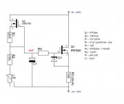
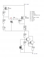
Why I used BJTs then, because sutable MOSFETS were not available to me then. Later I used MOSFETs in gyrators. Here is another example attached, with P-type MOSFET.
Why I used BJTs then, because sutable MOSFETS were not available to me then. Later I used MOSFETs in gyrators. Here is another example attached, with P-type MOSFET.
Attachments
No, it is because it keeps anode voltage stable, and dynamic load resistance is 470k that is much higher than internal resistance of the 12AX7 triode. Draw a load line and compare resulting distortions with distortions for the load line for a resistor that would be needed to get the same working point of the triode.
Why I used BJTs then, because sutable MOSFETS were not available to me then. Later I used MOSFETs in gyrators. Here is another example attached, with P-type MOSFET.
Distortion in a triode is mostly 2nd harmonic, so distortion is proportional to signal level. Or, looking at it another way, if you halve the signal level, you also halve the distortion. That's an important reason why most quality power amplifiers use negative feedback, but not preamplifiers.
There is a small amount of third order product - but this goes down even faster with signal level.
And neither is your P-channel MOSFET circuit a gyrator. Its' a simple AC ccs. Know where the word "gyrator" come from? It comes from "gyrate" - to spin, whirl. That's what a gyrator does - it sends a signal round and round between its TWO ports. Both ports are both input and output, like the windings of a transformer. What you do at one port causes something to happen at the other port, which with its termination, does something at the first port, which... Your circuit does not have this property, nor should it.
Using terminology and language correctly is the key to critical understanding. Sheesh.
A P-chan MOSFET makes a good ccs though. P-Chan's are more expensive than N though.
- Status
- Not open for further replies.
- Home
- Amplifiers
- Tubes / Valves
- Gyrator or CCS