absolutely trueJust so this is clear:
The circuit posted by hpeter is a CCS, not a gyrator.
It is as I said: It behaves as a CVS at DC, setting the anode voltage to approx. that of the first MOSFET gate supply, but the 1 uF capacitor off the tube anode makes the second MOSFET gate-source voltage constant for signal frequencies, so the drain current is constant and thus the dynamic anode load is very high - a CCS.
Keit
how to call it; it depends on amount of nitpicking we use.
better name perhaps; ac coupled source follower. ac coupled -is doing the high Z magic here.
if it was normal follower, then tube would see low Z, just like working into battery directly, without any load. (short)
Constant current supply should provide a constant current no matter ac or dc.
which here is not the cause, you can replace tube with short, and amperes will flow trough FET.
true ccs will give same mA no matter what V, doable with jfet,depletion fet, or a buch of transistor with fb.
few ccs examples
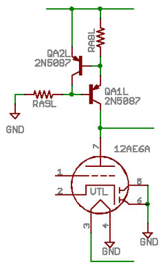
An externally hosted image should be here but it was not working when we last tested it.
Hpeter is correct in pointing out that his 2-MOSFET CVS/CCS circuit posted yesterday has a potentially nasty failure mode: If the tube shorts (or you slip with a voltmeter probe on the anode), then the current is uncontrolled and something will blow - probably the 2nd MOSFET.
But does a "true" CCS confer any advantage apart from that? Well, DC coupling perhaps, but a tube amp will be AC coupled elsewhere, even if only in the output transformer, so that isn't an issue.
The uncontrolled current problem of the CVS/CCS circuit is easily fixed by adding a resistor in series with the drain, and ensuring the MOSFET is rated to take the current limit set by the resistor.
The 2-transistor PNP/NPN CCS is not a good idea. If the tube shorts from internal flashover, a 200V transient is coupled by collector base capacitance to the base emitter junction, destroying the transistors, which short out. And then you have uncontrolled current again.
In the early 1960's, when small signal transistors with good performance and good collector voltage rating became available, hybrid circuits mixing transistors with tubes was very tempting. But factory engineers soon learnt that certain configurations (where bipolar transistors directly connect to tubes, especially anodes and screens) were good at destroying transistors, and should be avoided.
Keit
Note that you can make a good CCS that is a CVS at DC with a tube instead of a MOSFET. That's what they used to do in 1940's/1950's medical instruments where high gain and high reliability was required.
Only one triode is needed, preferably a high gm tube. The use of another MOSFET (or tube) to stabilize the bias is an overkill.
There is an important downside to a tube CCS though: Heater-cathode leakage in the CCS tube leads to hum being injected into the signal. So, use it where signal level is relatively high and choose the tube well.
Keit
i once had isolation breakdown on srpp, it also destroyed signal source. 🙁
since then i avoid tube on top at all times.
heater was lifted also a bit, but still..kaboom
fet does not damage the sound, since tube is doing all the gain.
ecc88 has 1,4pF Cag; with low cap fet you get <1pF Cgd (STM has few real good ones)
i must mention one model SiC from Cree, which can be used . C2M1000170D
just found a 1700V jfet, not bad. UJN171K0K
i once had isolation breakdown on srpp, it also destroyed signal source. 🙁
since then i avoid tube on top at all times.
......
Well, of course, you have to operate everything within ratings. Either choose a tube with sufficient heater-cathode voltage rating (tubes rated for series heater strings, and tubes designed for service as series pass devices in regulated power supplies usually (but not always) have adequate heater-cathode specs.
Series regulator tubes often have extra good heater-cathode insulation, and high gm - just the combination you want to make a CCS.
As you have found, you can have a separate heater supply for the top tube, pegged at or near the cathode voltage, but that has its own problems - usually hum and noise (solvable at extra complexity & expense), or the heater cathode insulation breaks down if the cathode gets shorted to earth (either by bottom tube flashover, or a slip with a meter probe.)
I believe a Very good option is the double mosfet CCS with a suitable resistor under..
then for fillament supply I intend to use a LT super Low noise regulator and a dual transistor CCS to set the disired app 3-4V bias and create the 1,4 V and 220mA over/through the parallel filaments 3A5/DCC90
So I use the regulator to set the voltage over and the CCC to set the filament current.. This will effectively keep the filament out of the Audio loop an create a firm foundation for the tube to oprerate.
Last edited:
MiiB, how do you figure that?
If you feed the paralleled filaments with a CVS supply, signal current splits in two in each filament and each part flows out of a filament pin. Four signals current in total.
The splitting is not equal, as one end of each filament adds to the bias more than the other.
If you feed the paralleled filaments with a double/split CCS supply with the centre tap earthed, same thing.
If you feed each of the filaments witb a single CCS, then ALL the signal current flows out of one pin. Is this situation worse? You will NOT hear any difference, except with deep bass. Deep bass causes a slight signal distortion (even order hrmaonic and some intermod distortion, due to te signal modulating the filament current and therefore heating, and the 3A5 being a quick heating tube intended for 2-way radio output stages (transmitter turned on with press-to-talk to save battery energy), the thermal time constant is quite short.
So, feeding filaments from a CCS causes MORE distortion. Off course, some tube fans like a bit of even order distortion - "tube sound".
Be aware that when filament tubes are operated with constant current filament heating, the current/voltage should be set a little low. This is because a tube filament's resistance is proportional to temperature. This means that when fed from a const voltage, the temperature is self regulating. If temperature rises, resistance rises, lowering the current. It is a thermal/electrical negative feedback loop.
If you feed a filament from a CCS, the CCS holds the current constant regardless of filament temperature and the temperature regulating effect is weakened.
Tube manufacturers used to recommend that directly heated tubes operated with series heater chains or const current supplies be operated at a lower filament voltage for this reason. Typically 1.3 V for a nominal 1.4V tube, and even then tubes failed more frequently than normal.
Certain rare tubes designed for telephone system repeater service, feeding with a CCS was the only way (the supply current was fed down the cable and supplied both HT and filament current). Tubes for this service had design features to make them reliable in spite of CCS feeding.
Before transistors, many manufacturers put out portable battery/mains radios with the battery type tubes (eg 1T4/1R5/1T4/1S5/3V4) filament in series. The total filament supply then adds up to 8.4V and can be fed from a nominal 9V carbon-zinc battery, or via a bleed resistance off the HT rectifier supply for mains operation. The bleeder resistance (which is effectively a CCS as it drops almost all the HT across itself) was recommended to be selected for a total filament voltage of 7.8 V.
And those of us that worked as radio/TV servicemen in the 1950's (including me) loved these battery/mains radios. Sell one radio, and over the next few years you sold a lot of tubes too, until the owner got sick of it, and bought a battery-only radio with the tube filaments in parallel. Despite the derated filaments.
Of course, running lower than 1.3V affects emission too much, and the tubes then fail early due to a different cause.
Note that the 3A5 is designed for intermittent 2-way radio service. Miniature batteries tubes were designed for a 1000-hout service life. The 3A5 life will be shorter. 1000 hours at 2 hours per day is only a year and a half. Now you know why when the first crude germanium transistors came on the market in the mid-1950's, battery tube radio sales stopped very rapidly, and lots of already purchased battery tube radios got scrapped.
Keit
Last edited:
<snip>
If you feed each of the filaments witb a single CCS, then ALL the signal current flows out of one pin. Is this situation worse? You will NOT hear any difference, except with deep bass. Deep bass causes a slight signal distortion (even order hrmaonic and some intermod distortion, due to te signal modulating the filament current and therefore heating, and the 3A5 being a quick heating tube intended for 2-way radio output stages (transmitter turned on with press-to-talk to save battery energy), the thermal time constant is quite short.
So, feeding filaments from a CCS causes MORE distortion. Off course, some tube fans like a bit of even order distortion - "tube sound".
<snip>
The 3A5 is capable of quick heating only when force-fed with the rated voltage from a low-impedance battery. It might draw 600-1000mA at startup, in this condition.
When fed more kindly, from a current-driven supply - which limits the current to its operating value of 220mA - the heating is much slower - maybe 4-5s.
Now we can consider the action of anode current at low frequencies. The normal anode current is 3.7mA. So a big bass note might involve a zero-to-peak swing of 1.5mA. This amplitude, if it were a dc shift, may have a minor effect on heating, after a minute or so - but it will not be fast acting. Extremely slow in fact: At 20Hz the measurable effect will be effectively zero.
<snip>
Be aware that when filament tubes are operated with constant current filament heating, the current/voltage should be set a little low. This is because a tube filament's resistance is proportional to temperature. This means that when fed from a const voltage, the temperature is self regulating. If temperature rises, resistance rises, lowering the current. It is a thermal/electrical negative feedback loop.
If you feed a filament from a CCS, the CCS holds the current constant regardless of filament temperature and the temperature regulating effect is weakened.
Tube manufacturers used to recommend that directly heated tubes operated with series heater chains or const current supplies be operated at a lower filament voltage for this reason. Typically 1.3 V for a nominal 1.4V tube, and even then tubes failed more frequently than normal.
<snip>
Such concerns may have been relevant in the 1950s, and may also apply to MiiB plan to use a simple uncompensated CCS: in this case the current will start 12-20% too high, and drift lower, which is not advisable.
But a correctly-implemented temperature-compensated current-driven supply will easily hold a stable value over temperature and long-time running, regardless of the filament type an behaviour. This is an observed and measured fact. The current must be fine-tunable, to allow the exact filament voltage to be achieved, and with a competent implementation, it should be set to exactly this nominal voltage.
I could also be possible to add a current mirror for each filament, and then mirror the currents in fed from the same voltage. This would effectively remove the influence from differences in impredance from the each filament. problem with that is off-course tha the tail end of each filament would have a slight difference in DC offset and thus put each section of the triode on a slightly different curve. I do believe that this offset would be less than the mechanical differnce of each section of the tube, and thus it will be of only academical interrest.
The 3A5 is capable of quick heating only when force-fed with the rated voltage from a low-impedance battery. It might draw 600-1000mA at startup, in this condition.
When fed more kindly, from a current-driven supply - which limits the current to its operating value of 220mA - the heating is much slower - maybe 4-5s.
Now we can consider the action of anode current at low frequencies. The normal anode current is 3.7mA. So a big bass note might involve a zero-to-peak swing of 1.5mA. This amplitude, if it were a dc shift, may have a minor effect on heating, after a minute or so - but it will not be fast acting. Extremely slow in fact: At 20Hz the measurable effect will be effectively zero.
This is essentially true in practice. I perhaps should have explained it a bit better. It is a case that feeding with a CCS theoretically gives additional distortion on deep bass, but you are unlikely to hear it.
It is essentially the same sort of problem as the use of a thermistor to regulate the output of wein bridge oscillators used as an "impeccable" signal source for distortion measurements. These oscillators typically show a rise in distortion at very low frequencies where the period is non-negligible compared to the thermistor time constant. An oscillator that might offer 0.002% distortion midband typically might offer 0.01% at 15 Hz. (eg my AWA low dist osc).
Rod's note that heating from cold to emission temperature is slower with const current feeding is true, but this is a red herring. What is relevant is that emission is approx. proportional to the 4th power of temperature. While the time from cold to noticeable emission might be seconds, the time taken to change emission a few percent is much shorter.
Last edited:
Such concerns may have been relevant in the 1950s, and may also apply to MiiB plan to use a simple uncompensated CCS: in this case the current will start 12-20% too high, and drift lower, which is not advisable.
But a correctly-implemented temperature-compensated current-driven supply will easily hold a stable value over temperature and long-time running, regardless of the filament type an behaviour. This is an observed and measured fact. The current must be fine-tunable, to allow the exact filament voltage to be achieved, and with a competent implementation, it should be set to exactly this nominal voltage.
Concerns of temperature driven variation in heater supply were not relevant in the 1950's example I gave - heaters in battery/mains radios were feed via a resistor for HT. The resistor was necessarily wirewound (typically 1800 ohm 3 watt or 5 watt). The tempco of such resistors is negligible.
It matters not a whit how good you design a solid state CCS for feeding filaments, or how carefully how you set the resulting filament voltage to the normal data-sheet filament voltage. Not how perfect its temperature stability is.
The problem is not with the CCS, it is within the tube.
What matters is that with const voltage feeding, the filament temperature is controlled by a thermo-electrical negative feedback loop. If filament temperature rises, filament resistance rises, current falls, and power drops - which must lower the temperature. So temperature variations are reduced.
With const current feeding, the thermo-electric feedback loop is positive. If temp rises, resistance rises, so voltage rises and thus power dissipation rises, pushing up the temperature even more.
I'm sure the aim is to listen to the nice music, not continually ride the CCS current pot as the tube ages. And even if you set the current so the voltage at the filament pins is "correct", variations within the filament length occur due to manufacturing tolerances. With CCS feeding, hot spot trouble is accentuated.
That's why tube manufacturers recommended that battery tubes be run 0.1 V low in series heater battery/mains radios - and even then tube failure was more frequent than for radios with filaments in parallel.
I am aware that there are a number of contributors on diyAudio that swear by feeding filaments with CCS's, but it is snake oil.
Keit

I understand perfectly well how the mechanism you describe is working, but it just does not make a practical difference: if you have a sufficiently stable current-driven regulator, the filament voltage is stable also, under all normal operating conditions.The problem is not with the CCS, it is within the tube.
I have used current driven heating supplies on a wide range of DHTs for over a decade, and can say, with absolute confidence that they do not require routine readjustment, even across thousands of hours use.
Others here that use my solution will be able to verify this for themselves.
This is essentially true in practice. I perhaps should have explained it a bit better. It is a case that feeding with a CCS theoretically gives additional distortion on deep bass, but you are unlikely to hear it.
It is essentially the same sort of problem as the use of a thermistor to regulate the output of wein bridge oscillators used as an "impeccable" signal source for distortion measurements. These oscillators typically show a rise in distortion at very low frequencies where the period is non-negligible compared to the thermistor time constant. An oscillator that might offer 0.002% distortion midband typically might offer 0.01% at 15 Hz. (eg my AWA low dist osc).
Rod's note that heating from cold to emission temperature is slower with const current feeding is true, but this is a red herring. What is relevant is that emission is approx. proportional to the 4th power of temperature. While the time from cold to noticeable emission might be seconds, the time taken to change emission a few percent is much shorter.
The real point is that the measured distortion due to this mechanism is effectively zero.
The real point is that the measured distortion due to this mechanism is effectively zero.
Agreed - because any such distortion will be even order, almost entirely 2nd harmonic, and that's what the tube grid-anode characteristic generates anyway, at a much larger amplitude within the audible frequency range.
As I said, it is solid theory that feeding filaments with a CCS generates more distortion than const voltage feeding, but you are unlikely to hear the difference, so why waste money time and effort on CCS.
I'm not going to say the difference cannot be measured, because some clever chap might device a method. One could measure at sub-audible frequencies and extrapolate down. And one could calculate it, the theory is quite simple.
In summary: CCS filament feeding = Snake oil.
Keit
I understand perfectly well how the mechanism you describe is working, but it just does not make a practical difference: if you have a sufficiently stable current-driven regulator, the filament voltage is stable also, under all normal operating conditions.
.....
Others here that use my solution will be able to verify this for themselves.
Measurements? Data?
And even if I accept it doesn't compromise tube life (and tube manufacturers did) what on earth is the benefit? You have accepted there is no sonic benefit.
Keit
Measurements? Data?
And even if I accept it doesn't compromise tube life (and tube manufacturers did) what on earth is the benefit? You have accepted there is no sonic benefit.
Keit
Measurements: Filament voltage of a variety of DHTs. All set to within 0.5% of the nominal value, and current fed.
Data: Rechecked regularly over long duration: including 300Bs right across their working lifetime (800-5000 hours, depending on the manufacturing quality). Result: No variation outside a 1% defined window.
The 'sonic benefit' of current-driven heating of DHTs is easily confirmed, and validated by more than enough constructors on this forum, that we need not worry too much about what you believe.
I have used current driven heating supplies on a wide range of DHTs for over a decade, and can say, with absolute confidence that they do not require routine readjustment, even across thousands of hours use.
Actual recorded data?
Were these power DHT's?
This thread is about the use of a 3A5, a battery oxide coated filament tube - a fragile device with a limited life at best.
Miniature battery tubes (eg the 1T4/1R5/1S5/3V4) were designed for only 1000 hours service (within specs). In practice they usually lasted a bit longer because radio typically worked ok down to 1.1 V per cell. The carbon-zinc technology gave a more or less linearly decreasing output until about 1.1 V. So the tubes only got 1.4 V when batteries were new.
1000 hours is not very long - 3 hours per day for one year, but batteries for tube radios were EXPENSIVE - it was important to minimize the drain, so tube life was sacrificed.
I cannot find design life for the 3A5, but it was intended for intermittent use in RF output stages of walkie-talkie radios, where the quick heat feature allowed the filament to be powered up only during press-to-talk. (actually, the most common use in my country was in radiosonde weather balloons - with an operational life of 30 minutes or so.) So, the life is mostly likely less than 1000 hours.
So, a 3A5 used in audio can be expected to wear out inconveniently quickly. I wouldn't want to make the situation any worse, though I know from my own experiments in my teenage years it makes a nice sound. I used to hike in the State Forrest and occasionally find a downed radiosonde, and retrieve the 3A5 and the relay.
CCS feeding DHT power tubes with thoriated tungsten filaments will also reduce their reliability/life, but they are comparitively rugged devices anyway, with thick wire filaments, not the barely visible fine wire of a 3A5.
Keit
Last edited:
I took the measurements, and satisfied myself that they were correctly taken. What do you expect - shall I hire a notary to act as a witness that I did what I said? Just to satisfy your idle curiosity?
If you are not content with my measurements, build your own solution, and measure it yourself.
I don't see any relevance to the rest of your remarks, and anyway, the 3A5 is not even a good DHT for audio, in my experience. Ale Moglia traced some curves for it recently (probably posted them here, too). Search the forum and see. But the results were poor compared with good stuff (4P1L, 300B, 45 etc)
And even if I accept it doesn't compromise tube life (and tube manufacturers did) what on earth is the benefit?
Keit
Please supply a trustworthy example (i.e. printed literature - not more paragraphs of unsubstantiated hand waving) of a valve manufacturer indicating that current-driven heating reduces filament life.
- Status
- Not open for further replies.
- Home
- Amplifiers
- Tubes / Valves
- Gyrator or CCS