Does anyone have any data (or estimates) of the DC saturation current in push-pull guitar amp output transformers? All the discussion I've managed to find on OT saturation seems to assume well matched average current across both sides of the primary, but this is not usually the case when the power amp is overdriven significantly. When a typical LTPI is overdriven, it exhibits significant bias excursion, causing duty cycle modulation of the output waveform. This means mismatched average currents in the output tubes and a DC component in the output transformer. Simulations suggest somewhere around 150mA of DC offset for a Marshall-style 50W power amp with the phase inverter driven hard.
That much?
Power tubes are symmetrical so take them out of the equation, and LTPI are also quite symmetrical.
I might expect important imbalance in a cathodyne PI and that has been proven many times, but not from an LTPI.
Which are even made more symmetrical by using different plate load resistors to compensate, such as in classic Fender/Marshall 82k/100k combo or Peavey 91k/100k .
The LTPI is pretty symmetrical until you drive it into grid current clipping. The average current through one half goes down because of the grid current, so the other half must go up in response. Here's the signal at the plates of a Marshall-style AC-coupled LTPI (82k/100k plate loads, 470R bias, 15k tail) driven with a 60V pk-pk 1kHz sine (Rs=100k) for 200ms:

And the AC-coupled output (0.022µ coupling caps, 220k load):

The input levels can go even a bit higher than this in the real circuit. Voltages vary with frequency because of the tonestack, but the output from the cathode follower before the tone stack is nearly 150V pk-pk.
The coupling caps remove the DC component, of course, but what happens when you put this signal into the power tubes? The bias voltage is about -40V, so slice each waveform off at +40V, and there's your grid signal (approximately... it will shift down over time because of the power tube grid current). So for this example, one power tube conducts for about 60% of each cycle and the other for about 40%. Both control grids go to 0V, so the peak currents are similar. Voilà! DC on the output transformer primary. For completeness, here's the current in the OT primary (resistive load), complete with PSU sag and ripple:

And zoomed to show the last 20ms:

The average current over this interval is -120mA.
And the AC-coupled output (0.022µ coupling caps, 220k load):
The input levels can go even a bit higher than this in the real circuit. Voltages vary with frequency because of the tonestack, but the output from the cathode follower before the tone stack is nearly 150V pk-pk.
The coupling caps remove the DC component, of course, but what happens when you put this signal into the power tubes? The bias voltage is about -40V, so slice each waveform off at +40V, and there's your grid signal (approximately... it will shift down over time because of the power tube grid current). So for this example, one power tube conducts for about 60% of each cycle and the other for about 40%. Both control grids go to 0V, so the peak currents are similar. Voilà! DC on the output transformer primary. For completeness, here's the current in the OT primary (resistive load), complete with PSU sag and ripple:
And zoomed to show the last 20ms:
The average current over this interval is -120mA.
Merlin Blencowe's "Designing Valve Preamps for Guitar and Bass, 2nd Ed" has a section on this. He says that proper bias voltage in the LTP is crucial - get it wrong, and one output tube can end up red-plating and being destroyed during heavy sustained overdrive.Simulations suggest somewhere around 150mA of DC offset for a Marshall-style 50W power amp with the phase inverter driven hard.
At the moment, I can't remember which was the dangerous direction to bias the LTP (warm, I think). And I'm at work, so I can't go check Blencowe's book for you.
Can you try tweaking LTP bias in your simulation, to see what that does to the amount of imbalance in output current?
120 mA of imbalance sounds like a lot - can the output tubes cope with that much increase in average current?
Also, I assume the usual measures to reduce bias shift and blocking distortion will also reduce the extent of this imbalance.
Taking a look at the larger picture, we all know that untested hypothesis are borderline useless. Still, FWIW, my untested hypothesis is that saturation in the OT is not nearly as important as some amp gurus say.
For starters, we have some gurus who say that small OEM transformers (Fender) sound best because they saturate easily, while on the other hand, we have other gurus who say that enormously overrated transformers (HiWatt, etc) sound best because they don't saturate. They can't both be right...
More objectively, if the transformer core saturates to any significant degree, electromagnetic coupling between primary and secondary windings weakens drastically, transformer action goes away, the impedance of the primary coil drops very low, and the output tubes end up trying to drive a load that's far too small.
So if significant OT saturation happens, you're also looking at endangered output tubes. No manufacturer who cared about reliability would let their amp designs go too far down that particular road. Ergo, I suspect that tube guitar amp manufacturers who have a good reputation, use output transformers big enough to avoid significant amounts of saturation.
As it happens, I have two different tube guitar amps which have very similar power amplifier sections, but one (Fender SuperChamp XD) was made to sell at a lower price, and has a smaller OT than the other ('65 Princeton Reverb reissue). At lower volumes I don't hear any real difference between the two power amps, but if you turn up loud enough, deep bass starts to disappear from the SCXD.
This might be because the smaller OT in the SCXD is beginning to enter saturation, starting to move into the curvy bits of the BH curve, but only for bass frequencies, which have the largest currents.
If that hypothesis is correct, the transformer begins to work poorly at low frequencies, and less bass makes it to the speaker; the small OT effectively creates a sliding high-pass filter, with cutoff frequency shifting upwards as output current is increased.
This is only a guess, so take it with a pinch of salt. It could just as well be the less capable loudspeaker in the SCXD "saturating" (running out of excursion), causing the same sliding high-pass filter behaviour.
Whatever the cause, to my ears, the sliding-filter effect is slight, and IMO, more or less irrelevant in musical terms.
-Gnobuddy
Both can, as long as their definition of "good" is different.For starters, we have some gurus who say that small OEM transformers (Fender) sound best because they saturate easily, while on the other hand, we have other gurus who say that enormously overrated transformers (HiWatt, etc) sound best because they don't saturate. They can't both be right...
Which seems to be the case, one group loves greasy squishy very elastic Blues sound, the others fast, dry, clean, analytical sound.
Note that I'm investigating the behavior of an existing circuit (Marshall 1987, in this case), not designing a new one. I'm not concerned with whether the behavior is bad for the tubes, only whether the simulation is accurate. The 12AX7 model (from Adrian Immler) I'm using appears to be highly accurate, so I have to assume the simulation is reasonably close to reality. Cranked Marshalls do blow up occasionally.
Also, this imbalance will occur any time a duty cycle modulated signal is fed into power tubes that are grid clipping. The duty cycle modulation could occur due to bias excursion in an earlier preamp stage, or in a pedal. Hendrix, for example, famously used a Fuzz Face, which causes extreme duty cycle modulation, into already distorted JTM45/100 stack.
Also, this imbalance will occur any time a duty cycle modulated signal is fed into power tubes that are grid clipping. The duty cycle modulation could occur due to bias excursion in an earlier preamp stage, or in a pedal. Hendrix, for example, famously used a Fuzz Face, which causes extreme duty cycle modulation, into already distorted JTM45/100 stack.
It seems to be close to center biased with the standard 470R bias resistor. I just tried 1k and 220R and there is some difference in the amount of duty cycle modulation, but it isn't huge. The maximum duty cycle (same test conditions as above) with 1k is about 60%, 470R is 61%, and 220R is 63%. Doubling the tail resistance to 30k reduced the maximum duty cycle to 59%.Can you try tweaking LTP bias in your simulation, to see what that does to the amount of imbalance in output current?
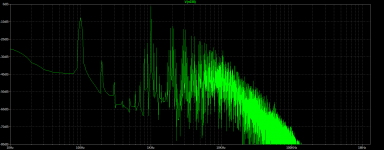
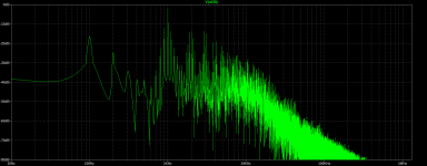
I found out that LTSpice has a couple nonlinear inductor models included, so I used the arbitrary inductor model to make a basic saturating inductor to represent the transformer magnetizing inductance (flux=L×Isat×tanh(x/Isat)). The test signal was 1kHz+100Hz sines at a 2:1 ratio (1kHz level was 55V pk-pk). With the magnetizing inductance saturating rather heavily, the RMS current increased by about 15% compared to no saturation. The 100Hz level was reduced (as one might expect) and IMD increased considerably (FFT attached).
Attachments
Pat Quilter has a few videos that show output waveforms of some tube amps: JCM 800 and Tweed Deluxe. In both cases, the slope of the clipped section of the waveform changes with the duty cycle. I'm guessing that this is caused by the effective magnetizing inductance changing with current offset. I don't see any evidence of severe saturation, however.

I think you've misinterpreted my intent. I'm actually trying to figure out how audible output transformer saturation is (if at all) so I can decide whether the effect is worth trying to emulate in a solid state circuit, not "fix" it in an existing tube circuit.
I certainly could have been more clear about the purpose of my question. I suppose I didn't expect to have my motives questioned 😉
I just looked up my copy of Blencowe's book. He suggests a 1k bias resistor (for both triodes) to minimize the amount of duty cycle shift. In his examples, the "tail" resistor is 22k, and both anode resistors are 100k.I just tried 1k and 220R and there is some difference in the amount of duty cycle modulation, but it isn't huge.
IMO Marshall has the most bizarrely unhelpful naming scheme of any consumer product manufacturer I've encountered. Isn't the 1987 is one of their older designs, dating from before they began to figure out how to make a good rock guitar amplifier?
-Gnobuddy
When, in your opinion, did Marshall start to make good amplifiers? Why are old Marshalls from the 1960ies so sought after?
Best regards!
Best regards!
Thanks. I don't see an enormous difference with those values, but there is some. Like I mentioned before, though, my intent is to reproduce the behavior of an existing circuit.I just looked up my copy of Blencowe's book. [...]
I certainly won't argue with that. "I use a 1971 1987 with a 1975 1960 and a 1978 1986 with a 1979 1982. I also have a 1966 1963." "... What?"Marshall has the most bizarrely unhelpful naming scheme of any consumer product manufacturer I've encountered.
The model 1987 the 50W lead-spec non master volume amp (schematic here), made from late 1967 through the JCM800 era (although the non-master JCM800s are rare). The 100W version is model 1959. The bass-spec amps are models 1992 (100W) and 1986 (50W). The master volume models (introduced in 1976) are models 2203 (100W) and 2204 (50W). More information here, if you're interested.
Many consider the JMP-era (1967-1981) non master volume amps to be some of the best rock amps ever made, sonically.
Yeah, this certainly is true. Although they operate somewhat digitally: With just a tiny action on the volume control, the amp gets from almost zero loudness to ear blasting sound levels.
Best regards!
Best regards!
Kay, to answer the second question first, I can only guess, but I think the answer is: most probably because Jimmi Hendrix used a Marshall amp, and tens of thousands of guitarists wanted to sound like their hero, and they thought/think that using the same amplifier will make them sound equally talented, rich, and famous.Why are old Marshalls from the 1960ies so sought after?
Jimi Hendrix’s Marshall Super 100 JTM45/100: (https://www.groundguitar.com/jimi-hendrix-gear/jimi-hendrixs-marshall-super-100-jtm45-100/),
If that wasn't enough, Eric Clapton famously used a Marshall Bluesbreaker (JTM45 combo), and his tens of thousands of guitarist fans also thought that they could sound like him if they bought the same amplifier.
Pete Townshend also used a JTM-45 (and was involved in testing the first prototype.) Jeff Beck supposedly has used Marshalls for much of his (long) career, too, though he is far too creative an artist to stick with one sound for years on end.
Never underestimate the power of blind imitation. It has sold millions of products over the years! 🙂
I have never used any Marshall amplifier, so I have no personal experience whatsoever with their big, loud, expensive, old monsters. That means I have no worthwhile opinion to offer, at least if its based on history.When, in your opinion, did Marshall start to make good amplifiers?
But from what I've seen on the Internet, the vintage Marshall amp that seems most beloved is the 50 watt 2204. This is the Marshall that can produce not only snarling rock sounds, but also beautiful clean tones. The same preamp was used in the even louder 2203, paired with a 100 W power amplifier instead of a 50 W one.
If you wanted to go deaf immediately, you could turn the master volume up to full, and sound like Clapton. If you wanted to lose your hearing a little more slowly and go deaf in a year or two, you could turn down the master volume a little.
Many years later, the 2203/2204 preamp design was still around. It surfaced unofficially in the AX84 co-operative DIY guitar amp designs (in the 1990s). It appeared again in the little Laney Cub amplifiers about ten years ago (2012), this time with a 15-watt power amplifier instead of a 100-watt one.
As for me, I have more interest in engineering than history. I don't care much which rich and famous narcissist used which amplifier. I'm more interested in what guitar sounds they were able to produce, and what circuits made those sounds possible.
When I look at the Marshall 1987 schematic, the only noteworthy change from older Fender preampifiers (which are themselves more or less taken from the RCA tube catalogue), is the colder-biased input stage on the bright channel, and the use of a smaller cathode bypass cap on the same stage. Marshall was already moving away, but only a little bit, from Hi-Fi preamp design, which is what Leo was still using (that's what Leo found in the back of the RCA tube catalogue).
By the time the Marshall 2203 preamp arrived, you can see considerably more design evolution. This was not just a copy of Leo Fender's preamp - it was modified to make it a better guitar amplifier. The 2203 has one more gain stage for larger amounts of overdrive, it has one extremely cold-biased "clipper" stage that adds a lot of harmonic texture, and it has a master volume so you can overdrive that DC-coupled cathode follower stage without blood pouring from your ears.
Even more interestingly, the 2203/2204 preamp was designed so that you could bypass one of the gain stages easily, and get some lovely clean guitar tone
by doing so. Jim Marshall may have been "The godfather of rock", but it seems he realized that not all guitarists played rock music all the time. With his 2204, you could get clean tones as lovely as any Fender Blackface amplifier, but you could also get snarling rock-guitar sounds, which no Fender amplifier of the time could produce. Win-win.
To me, the 2203/2204 preamp contains the foreshadowing of later switchable two-channel guitar amplifiers. Add a relay and a foot switch, and you're most of the way there. Add one more tone-stack (one for each channel), and one more master volume, and a few more poles on your relay, and you'd be all the way there.
As far as I know, Leo Fender never produced an amplifier with the same sort of versatility. He designed many amplifiers with lovely clean tone, but never thought to also incorporate the ability to make rock-music sounds. He (and the people he hired) never designed a guitar amp with the same versatility as the 2204.
I've posted the following link before, but Darryl Braun's You Tube review of a modern Marshall 2204 clone is a wonderful showcase of this vintage amplifier's tonal versatility. Clean tones start at about 7:10 into the video. Most of the rest showcases overdriven sounds.
-Gnobuddy
- Home
- Live Sound
- Instruments and Amps
- Guitar amp output transformer DC saturation current