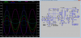
Yes definately, I'll have a good look at your schematic tonight. I have a 811a class A2 amp that I built and I like the sound of it, pentode could be worth a try but transformer impedance goes up. I'm crunching economics on power transformers ATM. I have a bunch to repurpose/rewindMe too also scare of voltage over 500V. But not everyone agree why one should stick to +-700V. It can deliver more than 30W with +-300 rail, or a total 600V. With SE amp you need about the same, I think about 500V on g2. Remember if you want more power with this tube drive it into A2, that should double the output power. Attached is Class A, can mod to A2, but I don't agreed everything in the snapshot (not mine): 150W?,in pentode mode.
You can do para feed so you can use PP type OT, need to use suitable choke to drive the OT with sufficient current more if into A2.
Hmmmm all top cap tubes, 807 driver..A2
Since one side of the output terminals is grounded
Really? the output terminal is never ground (directly), it's always connected to the load (600 ohms), if it's grounded (0 ohm) that will a short circuit and capacitor will overheat and gives out.
The AC voltages before and after the capacitor is almost the same (phase and amplitue) it thus passes AC and DC is blocked. You look at the voltage doubler circuit where e-cap is used to pass AC instead of transformer, in fact it's acting like one. Maybe someone can offer better reply than me.
Thank you for your explanation. Now I think I understand (that the AC voltages before and after C3 are practically the same).
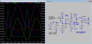
In order for the input stage to operate linearly, there must be a DC bias in the tube, generating a positive voltage across the cathode resistor. Try to drive the input (grid) too far negative, the tube cuts off leaving no voltage across C3. Won’t go negative unless the tube conducts backwards, which won’t happen. When you DO drive the grid with a larger negative excursion than the bias voltage, the feedback signal comes in behind it and drives the other end of the cathode resistor negative too, resulting in a positive voltage across C3 all the time. The resulting difference AC voltage across the grid-cathode ”junction” is small, and is the quantity actually being amplified at the plate.For AC current to flow at the output, there must be voltage swing, or? If so, than the voltage at the positive terminal of C3 has to swing up and down, or? Since one side of the output terminals is grounded, the swinging will take place around ground potential, or? If all this is true, than the positive terminal of C3 swings both positive and negative with respect to ground, or?
If the totem-pole circuit in post #7 is functioning properly, then the voltage at the junction of the lower tube's plate and the upper tube's cathode will presumably be more or less 0, when there is no signal. As indicated in the schematic, the capacitor C3 could be considered optional (i.e. it could instead be replaced by a direct connection to the output transformer). In normal operation, if C3 is included it will never have any appreciable voltage across it in either direction, and so it is fine for it it be an electrolytic.The (im)possibility of an electrolytic capacitor as C3 in the schematic in post #7 keeps nagging my brain.
For AC current to flow at the output, there must be voltage swing, or? If so, than the voltage at the positive terminal of C3 has to swing up and down, or? Since one side of the output terminals is grounded, the swinging will take place around ground potential, or? If all this is true, than the positive terminal of C3 swings both positive and negative with respect to ground, or?
If the above is true, how come that an electrolityc capacitor can be used as C3? I thought that the positive terminal of an electrolytic capacitor should always be positive with respect to the negative terminal, also under signal conditions.
So what am I missing. Am I wrong about the workings of the schematic? Or about what an electrolytic capacitor can withstand? Or am I wrong about both?
If, however, one were wanting to guard against the possibility of some catastrophic failure where one or the other of the output tubes effectively became a dead short, then there could be a problem with C3 as shown. If the upper tube developed the short it would be OK (from this point of view), as long as C3 could handle 700V across it; the polarity would at least be OK. But if instead the lower tube developed the short circuit that would put 700V in the wrong direction across C3, and that would definitely not be OK. If the aim of introducing C3 is to guard against such catastrophic failures, it should really be a bipolar capacitor, such as two back-to-back polarised capacitors connected in series.
An OTL such as the Tim Mellow OTL is a bit different because the mid-point of the +150V /0/ -150V power supply is not tied to ground, as far as DC is concerned. So probably with such a supply catastrophic failures that could put the loudspeaker at risk are not possible. But when I built mine I found that the midpoint of the +150V and -150V power supplies seemed too floppy and imprecise, and I ending up tying it to ground. This was a bit risky because catastrophic failures could then put the loudspeaker at risk. I got away with it for about 11 years, though. And when a failure did recently occur it just blew a fuse, so I was lucky.
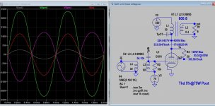
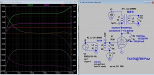
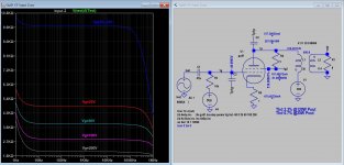
Here is SE A2 simulation for OP and and anyone who wants to persuade further. A2 in triode mode is better than A2 in pentode mode I deduced from sim. GU81 model file has been post to tube Spice page. This OT should work: https://sklep.toroidy.pl/en_US/p/TTG-6C33CSE-Tube-output-transformer-600-Ohm-6C33C/610, very low DCR (54 ohms) so output is higher.
Attachments
Last edited:
A2 triode looks like a good idea and falls within my specks. The off the shelf transformer is a great source of info. 600 to 8 ohms seems to me to be fairly easy to implement on on a diy scale in EI lams. I'm at risk of starting a new thread based on building an opt from scratch 600:8ohms... How do they allow DC current in a torroid? Cut a gap?
Firstly I'll get a chassis together with psu as I think I have a good starting point now. Updates on progress will come soon
Firstly I'll get a chassis together with psu as I think I have a good starting point now. Updates on progress will come soon
I think playing with the gu81 tube is going to be dropped due to the fact that with what’s going on in Europe rules out Russian valves. I had an order on its way that I placed unknowingly before hostilities began. I seriously doubt it will arrive and even if so spares will be unobtainable, the Shop owner in Russia is devastated to say the least for many reasons.
I would like to thank everyone for their input and advice.
If the parts arrive I will follow through to a degree (working prototype on the bench) but with no spare tubes, testing will be tricky as I cannot risk cooking a gu81.. I had already began to consider power supplies and put aside a bunch of laminations etc, I had also even began prepping up a few amorphous c cores salvaged from a 30kw 3ph solar inverter for the OPTs any transformers I now wind will need to be suitable for another output valve.
So where to now…
Gu81 alternate From the west or drop the project?
I don’t know.
There are some e-bay suppliers from the EU, for example from Romania:
https://www.ebay.co.uk/itm/253696299985?hash=item3b117a53d1:g:MVUAAOSw1ztbJ7An
https://www.ebay.co.uk/itm/253696299985?hash=item3b117a53d1:g:MVUAAOSw1ztbJ7An
Thank you, currently my parcel is cleared from customs waiting to fly out. Fingers crossed it comes. eBay is a funny thing sometimes I cannot see certain countries unless I use eBay UK etc, instead of eBay .au.
This is good I'll have to hold out and see, as for now back to the project then.
Cheers
This is good I'll have to hold out and see, as for now back to the project then.
Cheers
I'm looking at this schematic closely, how do I determine the dc current that the gu81 grid will draw? Am am I reading this correctly? 30v of swing into the Interstage transformer for 60v swing out to give approx 90w of output and the grid is held at +70vdcHere is SE A2 simulation for OP and and anyone who wants to persuade further. A2 in triode mode is better than A2 in pentode mode I deduced from sim. GU81 model file has been post to tube Spice page. This OT should work: https://sklep.toroidy.pl/en_US/p/TTG-6C33CSE-Tube-output-transformer-600-Ohm-6C33C/610, very low DCR (54 ohms) so output is higher.
Im keen to try an interstage transformer as this is something new in my builds. im assuming pick a tube that will swing 30v into a 5k load (maybie a SE 807 or 6l6 etc) or would this prove troublesome as there would be dc on both the interstage primary and secondary (gu81 grid current)
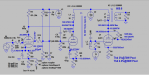
Attached snapshots show substantial grid 1 current of >50mA peak at 70W output, as A2 swing from>+100V to >-250V. IT would be 5K:600-1K rather than stated earlier (only good driven by Spice generator). So in real circuit the driver use could be 300b driven by 6e5p. The grid is bias at -70V, low secondary impedance IT could be the only way to be able to get large swing pass 0 into positive region. The grid appears drawn no current @-70V.
Attachments
Last edited:
That looks a lot more as I was expecting In a schematic or similar to other large transmitting valve audio output circuits. 50ma of grid current, I thought it would be significant and I need to put approx 300v p-p across the grid into a lowish grid impedance hence the large DC current (I think I understand this correctly)
I need to start simulating circuits myself it appears simple yet finding the time is tricky.. (young family) what is the software being used here as I'm keen to give it a go?
Just out of interest would someone be able to sim up the following as im after a ballpark set of values.
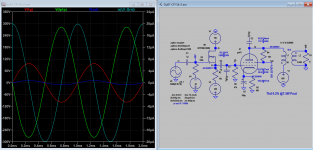
Gu81, Class A, 5k plate load, cathode bias resistor to ground, I'm assuming this is ok but uncommon. Maybie the filament won't like it or get in uneven potential across it. (Floaing the heater DC?) 600v on the plate approx 200ma max, triode connected, screen to plate via a resistor. 100ohm? Feel free to change the plate load
This is primative but getting a sound out safely and not killing a tube on the bench is my first step. Knowing the cathode resistor power and value really reduces the smoke getting out...
Tim
Just out of interest would someone be able to sim up the following as im after a ballpark set of values.
Gu81, Class A, 5k plate load, cathode bias resistor to ground, I'm assuming this is ok but uncommon. Maybie the filament won't like it or get in uneven potential across it. (Floaing the heater DC?) 600v on the plate approx 200ma max, triode connected, screen to plate via a resistor. 100ohm? Feel free to change the plate load
This is primative but getting a sound out safely and not killing a tube on the bench is my first step. Knowing the cathode resistor power and value really reduces the smoke getting out...
Tim
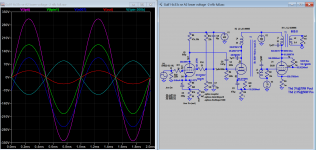
Attached maybe what you're looking.
DCR of OT is 50 ohms. 5k is not an optimal load in triode mode, you'll get more power in Pentode or UL mode if OT has got UL tap and you can switch one mode to the other.
The software used is LTSpice, you can download here: https://www.analog.com/en/design-center/design-tools-and-calculators/ltspice-simulator.html
Attachments
Thanks for the link, I'll jump on it and start playing.Attached maybe what you're looking.
DCR of OT is 50 ohms. 5k is not an optimal load in triode mode, you'll get more power in Pentode or UL mode if OT has got UL tap and you can switch one mode to the other.
The software used is LTSpice, you can download here: https://www.analog.com/en/design-center/design-tools-and-calculators/ltspice-simulator.html
- Home
- Amplifiers
- Tubes / Valves
- GU-81 OTL or other odd configurations