Hi folks,
in my efforts on learning on GU50 / SRS552 i have a few general questions.
Targets are two transformer sets Dynacord DCN027/DCN307. These are HiFi capable transformers (well, not high end).
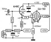
Target anode voltage is something around 750V and Raa=8kOhms, target power is 80W or slightly more. Obviously pretty interesting candidates for the GU50.
At present i am spicing some ideas for just a power stage, ideally with HiFi ambitions in order to prepare a prototype build.
This leads to the 1st question: grid leak resistance. How small must it be or better how large may it become?
The data sheets give no hints, at least for audio applications. I existing schematics i see a huge bandwidth, from 20k to 0.5 Megs.
I would actually prefer something near 100k (in order to avoid cathode follers as drivers) if that's possible.
2nd issue: screen voltage. The PT has an output for 245V~ If i use that as the bottom of the stack i'll end up with slightly more tha 300V, i.e. a little bit too much - especially if i decide to use a choke.
Will a SRS552 - the DDR version of the GU50 - handle this?
Is there a simple yet efficient way to reduce/stabilize the voltage?
How do i protect the screen from overload if i drive G2 form a low impedance source? IMHO that's neccessary in HiFi settings as well as in a bass amplifier - 80W with HiFi speakers is not very much.
in my efforts on learning on GU50 / SRS552 i have a few general questions.
Targets are two transformer sets Dynacord DCN027/DCN307. These are HiFi capable transformers (well, not high end).
Target anode voltage is something around 750V and Raa=8kOhms, target power is 80W or slightly more. Obviously pretty interesting candidates for the GU50.
At present i am spicing some ideas for just a power stage, ideally with HiFi ambitions in order to prepare a prototype build.
This leads to the 1st question: grid leak resistance. How small must it be or better how large may it become?
The data sheets give no hints, at least for audio applications. I existing schematics i see a huge bandwidth, from 20k to 0.5 Megs.
I would actually prefer something near 100k (in order to avoid cathode follers as drivers) if that's possible.
2nd issue: screen voltage. The PT has an output for 245V~ If i use that as the bottom of the stack i'll end up with slightly more tha 300V, i.e. a little bit too much - especially if i decide to use a choke.
Will a SRS552 - the DDR version of the GU50 - handle this?
Is there a simple yet efficient way to reduce/stabilize the voltage?
How do i protect the screen from overload if i drive G2 form a low impedance source? IMHO that's neccessary in HiFi settings as well as in a bass amplifier - 80W with HiFi speakers is not very much.
Hi Bea,
as of the Telefunken EL/FL152 datasheets a grid leak resistor of not more than 25 kOhms is allowed. This implies a cathode follower to drive these tubes correctly, i.e. from a low impedance driver.
Re screen supply: I don't have your PT's plate winding voltages handy, but I recall they're two different ones. In the original EL34 design the higher voltage one supplies the screens and the ECC81 PI tube. You might swap both windings to yield about 300 Vdc for the GU50 screens, but then the Cathodyne's supply voltage would be too low to drive the GU's sufficiently (which call for 3/2 as much drive signal compared to the EL34's) or you leave them as they are and provide a choke input filter or a passive DC regulator for the screen supply.
Best regards!
Last edited:
Hi,
of course i do swap the voltages and even try to add the 45V winding. That should be no problem at all with the Welter transformer, but the DCN027 seems to have a weaker 45 winding (roughly 2/3 of the current, concluded from the fuses).
I know the number for the grid leak in the FL15s data sheet. But as far as i recall the LS 50 specs are for some specific RF application, and even more, the circuits from that time have very large grid leak resistors.
And @Wavebourn's Pyramid design has large grid leak resistors as well - really large compared to the 25k. So i am not sure how the strict the specs have to be taken in that respect. Just from seeing this i have the impression that the GU50 is in that respect more similar to, say, a 6L6GC which in some RF applications also needs small grid leak resistors.
So the additional question: how is the grid leak determined? There must be some physical property (the charge accumulating on grid 1) that can be measured.
Interesting, I'm breadboarding a GU50 pentode PP, so far I followed Wavebourn regarding grid leaks. A lot more than 25K, so I got a bit worried. I haven't tested the output stage yet.
The range of safe grid leak resistances is dependent on whether the tube is using fixed bias, fixed adjustable bias, or self bias.
The GU50 is an RF tube, so it was probably very seldom used with self bias.
How will you bias your GU50 tubes?
The GU50 is an RF tube, so it was probably very seldom used with self bias.
How will you bias your GU50 tubes?
As the EL34's in the original design are fix biased, I guess she's gonna do that, too.
Best regards!
Best regards!
Fixed bias, adjustable, of course. At a target power of ~80W self bias is usually not useful.
But anyway, Wavebourne's Pyramid amp is also fixed adjustable bias; its grid leak resistance is somewhere around 170-180k.
Back to the physics: The reason for a grid leak resistor is that the grid catches some electrons und thus accumulates charge which must be transported off the grid in order not to shifts the bias. Which happened to me accidentally when i modified an EL84SE amp where the grid leak resistor lost its contact to ground...
To me it is quite obvious that this depends on the current through the valve, the grid geometry and the bias voltage. For a given tube less current and larger bias voltage (colder biasing) should mean larger grid leak resistors. Which You actually find in a few data sheets, i saw it for either the KT77 or EL34.
Which means that Class A is more critical to the grid leak resistor than Class AB or even Class B.
BTW: in the original EL34 power stage where my transformers com
by Dynacord the grid leaks are also larger than the specs if You add up all resistances along the grid leak path - not much, about 40 kOhms.
Back to my question: there is of course a pragmatic approach: oberve the quiescent current over time or even better during intermittent heavy load.
The GU50 is an RF tube, so it was probably very seldom used with self bias.
Here two self biased examples - the RL12P50 are the same systems LS50 in a different packaging:
http://www.jogis-roehrenbude.de/Verstaerker/RL12P50.jpg
http://www.jogis-roehrenbude.de/Verstaerker/LS50-Mehrk1.jpg
Note the grid leak resistors - similar to 6L6 with self bias.
Run the 80 Watt amp with a 20Hz signal at various power levels from 10W to 80W.
(20Hz gives the reflected load in parallel with the transformer primary inductance).
The maximum tube dissipation will occur somewhere at those power levels, probably between 20W to 60W.
You could determine that by close study of the tube curves, the reflected load in parallel with the primary inductance, and the volt x current area of that curve at those plate excursions at those power levels.
At maximum tube dissipation, the tube gets the hottest.
That is where there may run-away.
If it passes that, it has been subjected to the acid test (Well not exactly, use the lowest load impedance the amp will see, and use a resistor of that value, i.e. a 3 Ohm resistor on the 8 Ohm tap.
Which for a quick and dirty 1st check would reduce to "attach my two 8 Ohms load resistors to the 8 Ohms tap and observe the output at 18V RMS (~40 Watts into 8 Ohms) and observe the stability of the cathode current", shouldn't it? Over what timespan would You recommend?
BTW: the Telefunken data sheet for the EL34 shows the situation for the corresponding case with EL34 (example 11, 100W, Raa=11k). The diagram shows the anode dissipation having a very flat maximum in the range You mentioned. I expect something fairly similar for the GU50 case.
BTW: the Telefunken data sheet for the EL34 shows the situation for the corresponding case with EL34 (example 11, 100W, Raa=11k). The diagram shows the anode dissipation having a very flat maximum in the range You mentioned. I expect something fairly similar for the GU50 case.
Maximum plate power dissipation in a class AB amplifier can be expected when driven to about two thirds of the maximum output power.
Best regards!
Best regards!
Yes, thats's the theory. Study the example i just mentioned and You see how flat the maximums actually is. But back to the GU50 - AFAIK, Wavebourn's amp is biased pretty cold. Maybe that's also a precondition to be able to use a larger grid leak resistance?
The old LS50 designers must have had a lot more data available than documented in the official data sheets. Hint: the example i showed has a grid leak resistor larger by a factor of 20(!) than what we believe to be the upper limit. That's far more than the factor of 3-5 we usually read in tube specs. That's what makes me believe that the datasheet (of the FL152 or LS50) is unrealistically strict or more probably incomplete in that respect.
The old LS50 designers must have had a lot more data available than documented in the official data sheets. Hint: the example i showed has a grid leak resistor larger by a factor of 20(!) than what we believe to be the upper limit. That's far more than the factor of 3-5 we usually read in tube specs. That's what makes me believe that the datasheet (of the FL152 or LS50) is unrealistically strict or more probably incomplete in that respect.
If you drive the GU50 with a cathode follower then there is no grid leak problem.
And with the Raa=8k the Va doesn't go under 150V, not much to worry about exessif screen current.
Mona
And with the Raa=8k the Va doesn't go under 150V, not much to worry about exessif screen current.
Mona
Attachments
Last edited:
If you drive the GU50 with a cathode follower then there is no grid leak problem.
And with the Raa=8k the Va doesn't go under 150V, not much to worry about exessif screen current.
Mona
Some of us would rather not use a cathode follower.
Shure, would make this threat useless 😀Some of us would rather not use a cathode follower.
Mona
If you drive the GU50 with a cathode follower then there is no grid leak problem.
I know. And i actually have set it up in LTSPICE.
But sometimes there are reasons where You might be happy coming along without cathode follower.
Moreover: i want to get some better understanding of that tube. And if there is some indication that the 25k grid leak might be too restrictive i find it useful to understand why and how. Just from curiosity.
Regardng G2 load: up to now my simulations were all safely below 5W G2 load. Even at 95W. But i did not check really overdriven situations, where grid current might get large.
The GU-50 works very well in PP AB2 mode. The given periphery, especially the OT and PT, literally calls for this. How else would you deliver grid current to this tube?Some of us would rather not use a cathode follower.
Best regards!
Indeed. But my 1st impression is that especially the PT is a bit limited that so You will not be able to make use of that potential. Morover, if You use the 45V winding, You'll be limited to a sustained anode current of ~90 mA - that's what the solid state stages of the Eminent draw. THe corresponding transformer from Welter will deliver more - its winding is specified to 260mA as well.
I think it'll depend on how much capacity will be available if the heaters of the pentodes are taken from a separate 12V supply.
Actually my simulations give bout 80-95W independent on the driver (ECC81 or ECF802 based cathodyne with or without ECC81 based cathode followers.)
I think it'll depend on how much capacity will be available if the heaters of the pentodes are taken from a separate 12V supply.
Actually my simulations give bout 80-95W independent on the driver (ECC81 or ECF802 based cathodyne with or without ECC81 based cathode followers.)
- Home
- Amplifiers
- Tubes / Valves
- GU-50 grid leak and G2 questions