Back to the grounding issue
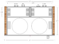
I'm not an expert (mechanical engineer, but I've hung around with sparkies for 30 years), but it appears that if the grounds are wired as diredted you wind up with a ground loop. There's a 180-degree twist in the loop, which should give some immunity to uniform fields, but it might still be sensitive to local fields from the transformer.
The loop would be avoided if you run one lead from PG+ on the PS board to one amp, PG- from the PS to the other amp, and then tie them togerther, either on the PS board (PG+ to PG-) or between the two amp boards. This should give you a star ground.
With luck, pictures should appear below (this is my first post). Black lines are wires, blue lines are traces on the boards.
Comments?
Phil
You will always end up with loops, if using two bridges and separate ground lines from ea. bridge.
If you are concerned about those loops, you can tie both grounds together at the rectifiers board and run a single ground wire to each amp.
If you are concerned about those loops, you can tie both grounds together at the rectifiers board and run a single ground wire to each amp.
It's arrived!!!
The wife just rang me from home......
"You have a package from Brian Bell"
It's a shame it didn't quite get here last friday, as it would have been a fitting birthday present to myself.
Now, how can I make an excuse to leave work early???
It looks like I'll be busy tonight......
........... and the next night.
............and a few more after that too.
I got my boards last night! Couldn't wait to rip open the package, inside I found a nice little padded envelope, saying that it contained a PCB order, and a bonus 😀 Thinking that the bonus was the resistor pack that Brian had mentioned, I was shocked to see that not only did Brian include the resistors, but also an extra set of boards! Wow Brian, that was increadibly generous of you, THANK YOU! I had been debating about what kind of gainclone to build, I need a simple one for testing loudspeakers, just a small portable amp, doesn't have to sound good, just be functional, and I also wanted to build one with all premium parts, good volume control, and a spiffy case. Now I can do both 🙂
Once again, thanks Brian (and Mere), I will post pics once I have the first amp done (will be working on it tomorrow night, my wife is going out with the girls and I will have time to put it together).
Cheers,
Ron
Once again, thanks Brian (and Mere), I will post pics once I have the first amp done (will be working on it tomorrow night, my wife is going out with the girls and I will have time to put it together).
Cheers,
Ron
Just received 8 kits (for me and some friends).
The soldering party is scheduled for next weekend! 😀
Thanks Brian!
The soldering party is scheduled for next weekend! 😀
Thanks Brian!
mstol said:Just received 8 kits (for me and some friends).
The soldering party is scheduled for next weekend! 😀
Thanks Brian!
Lucky bast@rd 😀 😉

Would this concept work if I built a chasis like this and used one side intitially with the kit I have allready and then add the 2nd side after I we figure out the best way to bridge? Thi way I could have a 70 -100 Watt 2 channel amp? I'd use a Avel 330VA 25V+25V transformer for each channel.
Attachments
kestrel200 said:Would this concept work if I built a chasis like this and used one side intitially with the kit I have allready and then add the 2nd side after I we figure out the best way to bridge? Thi way I could have a 70 -100 Watt 2 channel amp? I'd use a Avel 330VA 25V+25V transformer for each channel.
I see no reason why it wouldn't work, as long as you add extra output jacks for the extra channels. The extra width on the rear panel should help.
Bridging might be more difficult with the existing setup, but biamping would work great, or a great amplifier for a 4 channel active crossover 2-way system.
I thought about this for a while myself, and decided to just build 2 - 2 channel chassis (or buy 2 from Peter) instead of a 4 channel.
--
Brian
Just took a look at the user manual.
http://www.BrianGT.com
Very nice. Perhaps I'll even read it before I stick my boards together.
-Dave
http://www.BrianGT.com
Very nice. Perhaps I'll even read it before I stick my boards together.
-Dave
Brian I appreciate you replying...but aren't you on your honeymoon??? Meredith must be the most understanding wife in history. Does she have any older, single sisters withe the same understanding dispositions??
kestrel200 said:Brian I appreciate you replying...but aren't you on your honeymoon??? Meredith must be the most understanding wife in history. Does she have any older, single sisters withe the same understanding dispositions??
heh.. I am putting off the honeymoon for a while, as I want to save up some cash and plan something worthwhile, like a trip to Japan or something.
She is quite an understanding woman, but I think a lot goes along with her going to Georgia Tech with me and graduating as an engineer (chemical engineer). She was with me before I started my audio projects (I met her 4.5 years ago, and only started audio projects a little over 2 years ago).
For everyone participating in the group order:
All the kits have been mailed out, as of today. Meredith took the last batch to the post office. All kits that were mailed out today received a bonus pcb, to compensate for being mailed almost a week later than the rest of the kits. (12 orders mailed out today)
--
Brian
Brian,
How 'bout them Yellow Jackets? I think they're going to go all the way! ...nothing beats March Madness 🙂
How 'bout them Yellow Jackets? I think they're going to go all the way! ...nothing beats March Madness 🙂
BrianGT said:For everyone participating in the group order:
All the kits have been mailed out, as of today.
Mine too? I'm itching to get this puppy off the ground 🙂
dave
BrianGT said:
heh.. I am putting off the honeymoon for a while, as I want to save up some cash and plan something worthwhile, like a trip to Japan or something.
She is quite an understanding woman, but I think a lot goes along with her going to Georgia Tech with me and graduating as an engineer (chemical engineer). She was with me before I started my audio projects (I met her 4.5 years ago, and only started audio projects a little over 2 years ago).
For everyone participating in the group order:
All the kits have been mailed out, as of today. Meredith took the last batch to the post office. All kits that were mailed out today received a bonus pcb, to compensate for being mailed almost a week later than the rest of the kits. (12 orders mailed out today)
--
Brian
Today I received the package from You.
Many thanks for your effort
Ben
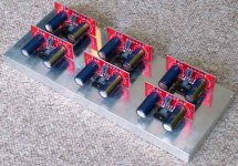
debije said:Would this setup work for a 6 channel amp? Size of the aluminium bar is 300x110x20 mm. PCB's will be facing the rear panel.
Should I use solid core wiring to wire everything up or stranded core?
Rob.
That setup should be fine. I would say that after playing for a while, the bar will get pretty warm, but I would not expect it to really feel hot to the touch. If the bar will be completely inside your chassis, I would recommend some ventilation holes on the bottom and top to let the hot air out. As for the wire, I cant really say, but solid-core does have the advantage of staying where you put it. Personally, I think that if you have the solid-core wire, I would use it for the power connections, and use good stranded wire for the signal connections, but again, that's up to you, and I would recommend taking other people's advice over mine.
How big should the heatsink be for a gainclone?
More or less.
It obviously is not such a problem as on the Pass designs..
More or less.
It obviously is not such a problem as on the Pass designs..
- Status
- Not open for further replies.
- Home
- Group Buys
- Group order of non-inverted LM3875 pc boards? Anyone interested?