Are there any boards left? Can I add myself to a list?
Thanks,
Ron
Yes, I have new boards coming. You can send me a PM, include address and phone number please.
Jan
I have received several questions for a version of the regulator that can handle more than 600V max. The issue here is the voltage handling capacity of the pass device Q1 MOSFET, and the capacitors C3, C4 and C6. Q8 is rated for 1kV so there's some leeway there.
The problem with finding a higher-voltage Q1 is the SOA (Safe Operating Area). In case of short circuit, the full input voltage is across Q1 with the current at maximum. The used device can handle 600V at 400mA.
The FCP850N80Z can handle 800V and has a reasonale SOA, max. 200mA. So if you set the current limit to 200mA max, this setup would be good up to 800V.
You can replace C3 and C4 with 0.03uF/800V, mouser part number 667-ECW-H8303JV. They should fit the PCB.
Unfortunately I could not find a drop-in replacement for C6 that could handle 800V. Mouser part # 871-B32774P8105K000 is an 840V box film cap with a pin pitch of 27.5mm. This will not fit the PCB directly but you may be able to jury-rig something up, for instance mounting it on the bottom side.
Hope this is useful but note I have not tested this! If you do go this route, I'd like to hear from you, how it worked out.
Jan
Last edited:
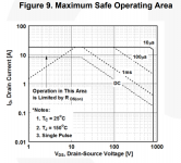
To add to the above, here is the safe operating area for that 800V FCP850N80Z MOSFET. Remember that at short circuited output, all the input voltage is across the MOSFET, and to be safe we want to make sure that it can withstand that dissipation indefinitely* .
So if your input voltage is 800V (max allowed), you see that the max current limit is about 200mA.
You also see that if you want to set the limit to 300mA, the max input voltage is about 400V. IF you work at 400V, it is better to use the original 600V FDP12N60, which can handle 400mA at up to 600V (see its data sheet SOA graph).
* In my circuit, the regulator will be shut off in a few 100ms but unless you have an infinite heatsink, it should be treated as DC.
Jan
Attachments
Heat sinks
Hi Jan,
one question:
Q1+ Q8 are on the same heatsink. Right?
What about Q7 does it need a second heatsink? If so is a small one sufficient?
My current f.e. is about 40 mA, the voltage drop between raw input and Vout is less than 50 V.
All the best for the new year by the way
Hi Jan,
one question:
Q1+ Q8 are on the same heatsink. Right?
What about Q7 does it need a second heatsink? If so is a small one sufficient?
My current f.e. is about 40 mA, the voltage drop between raw input and Vout is less than 50 V.
All the best for the new year by the way
Q8 is the current source and should be on the 'inside' of the heatsink.
For the pass device you use either Q1 or Q7.
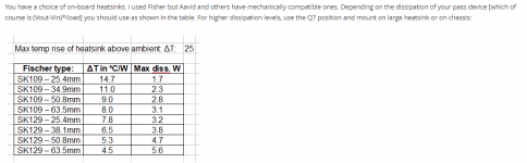
For pass device dissipations up to say 5 or 6W you can use the Q1 position on the outside of the heatsink.
For higher dissipations, use the Q7 position on an external heasink or bracket.
In either case, Q1/Q7 is only one device, the same device. All documented online here:
T-reg HV regulator | Linear Audio NL
Jan
For the pass device you use either Q1 or Q7.
For pass device dissipations up to say 5 or 6W you can use the Q1 position on the outside of the heatsink.
For higher dissipations, use the Q7 position on an external heasink or bracket.
In either case, Q1/Q7 is only one device, the same device. All documented online here:
T-reg HV regulator | Linear Audio NL
Jan
Attachments
Jan,
got it on the heatsink issue. Do you mean that you need onlyQ1 or Q7 not both?
By the way are there 2 more PCBs available?
Best
got it on the heatsink issue. Do you mean that you need onlyQ1 or Q7 not both?
By the way are there 2 more PCBs available?
Best
Jan,
got it on the heatsink issue. Do you mean that you need onlyQ1 or Q7 not both?
By the way are there 2 more PCBs available?
Best
See post 128.
I have more PCBs on the way, they are in-country so should be delivered coming week.
Jan
Dear Friends,
I ordered high-voltage regulator boards some time ago planning to send them out last week. Unfortunately, the Belgian Customs decided that this time they would select my shipment to turn upside down. I received lots of forms to fill out and they will process that hopefully this week.
The problem is that I am not home for at least another 6-8 weeks, so earliest shipping would be mid-March.
I know that several of you have already paid their boards. If you don't want to wait, let me know and i will reimburse you. If you can wait, no action required, I have you logged.
Apologies for this delay, I regret it but can't change it now.
Jan
I'd like two boards and have added myself to the list below.
Waiting list:
siddv 2x
fbjohn 1x
shattered_dream 2x
adams_leo 2x
YouAgain 2x
Waiting list:
siddv 2x
fbjohn 1x
shattered_dream 2x
adams_leo 2x
YouAgain 2x
- is there a way i can ask this anonymously .... here's the give away silly newbie question , do you need 1 board or 2 per amp?
My question is if I order two boards will I get both Positive and Negative (which is what I'd like).
The high voltage regulator only exists as a pos output board. But you can ground the output and use the neg side as neg output. No change in performance. Just make sure the transformer winding is correctly connected or floating.
Jan
Jan
- is there a way i can ask this anonymously .... here's the give away silly newbie question , do you need 1 board or 2 per amp?
Does your amp need two different voltages?
Jan
The high voltage regulator only exists as a pos output board. But you can ground the output and use the neg side as neg output. No change in performance. Just make sure the transformer winding is correctly connected or floating.
Jan
Perfect! Thanks again for all the great things that you have provided to the DIY community.
- Home
- Group Buys
- Group Buy for Jan's high voltage regulator