Thanks.
Theob, thanks.
And isn't this better than the vituperative stuff on AA about this tweak?
FYI, I'm 'bartc' there.
Theob, thanks.
And isn't this better than the vituperative stuff on AA about this tweak?
FYI, I'm 'bartc' there.
I have no idea where we might go to obtain actual data on battery usage as a ground plane charge device. One of the AA posts indicated that using a battery ground lug to attach to electrical equipment in a space environment dramatically lowered the noise floor. There were some disputations from others of course. Likely the usual AA sour grapes over not having been quite clever enough....
I look at the return side of single ended electronics as a zone where there are a minimum number of electrons inhabiting the outer orbits of the copper atoms. Just the opposite of the plus side, where the driver is providing as full a charge of electrons to available orbits as possible, between driver and load impedance.
This is of primary importance during the E field moment when the signal attached to the wave guide must halt and change vector, to flow back through the load. With a full ground plane near the signal side circuits, the constant effects of E Fields through dielectric materials, which draw electrons into a specific area, will clump into a fully charged area under the plus side circuit. Electrons do not travel very far or very fast, mostly they just seethe in random Brownian motion until frozen for a moment by a vector change. So this continual E Field gathering process will keep them local to the area under the plus side circuitry. Adding a dielectric with a relatively low charge threshold, in a triboelectric sense, will just aid in this process. The net result is less lost information from the signal during the E Field moments, hence a better signal to noise ratio and a greater information coherence to the back wave as the signal is drawn back through the load.
The Ground Control devices mimic this portion of full ground planes. They are a very low RAC / RDC loop of wire (140 strands of #40 AWG insulated, 5 nines copper, coil winding wire). Since they are made with true braided Litz wire they are relatively immune to airborne EMF and proximity effect. All of this adds up to a lower impedance "well" for ground side electrons to seethe into, fill all available orbits within and then provide a huge, low loss, unterminated wave guide for the signal to "ring" in while awaiting the E Field moment vector change, that will draw it back across the load. Obviously only a fraction of the signal performs this, but it is enough to provide greater audible back wave coherence.
We should be able to measure this effect with the same methods used to look into the benefits of using full ground planes. Assuming of course there are tests aimed at describing the functions of ground planes.
And yes Marc, strip ground, commercial, reinforced insulation, audio components are particularly susceptible to audible improvement with these GC devices. Fully differential equipment is immune as are most applications using a full ground plane.
Bud
Bud, have you been hanging out with "danielwritesbac" and "Distroyer OS." ?
As your posts are starting to resemble theirs.
As your posts are starting to resemble theirs.
Budp or others with experience: can the groundsides be used on pwer supplies grounds even digital ps grounds?
I wouldn't use them on SMPS, again due to fast and high current switching, re the same reasons I wouldnt use them on digital equipment. For SMPS they will act as transmitters of the harmonic noise from the switching, which is hard enough to control in the first place.
Linear, I dont know.
Linear, I dont know.
Budp or others with experience: can the groundsides be used on pwer supplies grounds even digital ps grounds?
I think it was warned about NOT to use on anything digital. Of course I had to try my self on my SD card player/ Buff dac PS star ground and yes, bad move. I really thought I hurt something. Dropouts, ticks, pops, it was scary for awhile even after the device was removed. All is OK now though.
Wanted to mention also something about how I prep magnet wire. I have a big ugly soldering iron, about 150-200 watt with a large flat tip about 1.5 in wide. This was enough heat to melt the enamel when used with acid type flux. Just make sure the acid flux does not drip down the useable part of the wire and you are good to go. I cleaned each end with alcohol before soldering all the ends together. In case some people have a big iron but no solder pot.
BudP, these little devices are great. Noticeable improvement when used on the star ground of my F5's, and at the minus on the back of speakers.
MMMHMMMM drop outs, check, pops n clicks, check, complete recovery, check..... did you try it on the analog out of your DAC yet? Second best place to put these things. Then you might just try the commercial version on your speakers. You will find additional attributes available.
Bud
Bud
did you try it on the analog out of your DAC yet?
Waiting for more wire, but that is the next place I will try.
I wouldn't use them on SMPS, again due to fast and high current switching, re the same reasons I wouldnt use them on digital equipment. For SMPS they will act as transmitters of the harmonic noise from the switching, which is hard enough to control in the first place.
Linear, I dont know.
Marce: I use LiFePo4 batteries as my sound card digital supply and my Buf32s digital power supply. So both are linear. But by accident I put some groundside simulators on my sound card ps and it worked fabulously until I remembered something about no digital , so I pulled it out quickly. No damage but there was 10 seconds or so of sublime music. Yea I'll refrain in the future.
Very curious about these devices.
I have a CD player and phono preamplifier without any spare RCA sockets.
Not wanting to open up the case...
1) Is it possible to attach the device to the ground (RCA collar) of one of the analog RCA output connectors?
2) For the phono preamplifier is it possible to attach the device to the grounding post.
It also mentions in the post that connecting them to digital input or output ground is not a good idea. Is there any harm in trying them there? What should I look for as adverse effects?
Is it possible to attach the device to the ground (RCA collar) of one of the analog RCA output connectors?
Yes, if you are making your own out of Litz wire it is possible, but, unless you have a solder pot to strip the coating off of the wire with, it is going to be difficult to do. You can also apply them to the negative lug of a cable and run them out the same hole the cable exits the RCA from. Again, not easy. If you purchase one of the Audio Prism Ground Controls, you can simply attach an RCA Wye connector and connect the Ground Control RCA plug there.
For the phono preamplifier is it possible to attach the device to the grounding post.
It is of course possible. However it will not affect the performance of the preamp to the degree that applying it directly to signal return ground will. The phono ground lugs are usually connected to the chassis and go to ground at the true ground wire at the IEC plug. This is not a useful place to attempt to modify the ground characteristics of the signal return from.
It also mentions in the post that connecting them to digital input or output ground is not a good idea. Is there any harm in trying them there? What should I look for as adverse effects?
So far, every connection experiment to a digital ground, without any buffer, has resulted in disaster. So far, nothing completely permanent, but one CD player I know of now refuses to play the entire disk of some SACD recordings that it played just fine before the digital ground was abused.
Bud
So far, every connection experiment to a digital ground, without any buffer, has resulted in disaster.
Yeah, PCM signals can be finicky. But I think the theory that ground effects can result in higher fidelity (lower jitter) in the digital PCM domain is supported by an observation I made. I had to replace the motherboard of the computer that drives my 'main' sound system. The DIY electronics and speakers were good but not 'over the top' [This was before EnABL treatment. Now that the speakers are EnABL'd they sound 'over the top'! 🙂] As luck would have it, I chose a brand of motherboard that had double the amount of copper in the ground and power planes, ostensibly for heat management. The improvement in sound quality was not subtle - it was clear and consistent. GIGABYTE USB 3.0 Motherboards
Since I've been messing with balanced amps it has struck me that there is some kind of hidden benefit to centering the ground. I mean, you can take two otherwise unimpressive amp circuits and oppose them in a balanced configuration and they sound waymobetta! To rationalize that, the argument that balanced signals reject common mode interference seems very insufficient. The argument that power supply load is relatively constant is obviously plausible, but not in line with the sonic improvements. But could it be that the *grounds* are better mannered when there is a push-pull on them, rather than a single-ended push-push?
Frank
True differential amplifiers have no need of Ground Control. Both sides of the load are charged with electrons, which migrate rather than flow. Their activity has been described to me as jitter with a direction.
An actual ground plane has more functions than the loop of wire with plastic bits. Unfortunately, in modern electrical environments like the air we are in, a true ground plane is too good an antenna, unless careful case shielding has been implemented. Better to just go fully differential really, much as I enjoy selling Ground Controls to those who actually do need them.
Bud
G'day All,
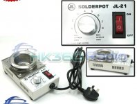
Just bought myself a solder pot for GBP 21 including delivery (around AU$30)
JL-21 Solder pot 250V 150W 200~430°C (eBay item 150553393643 end time 23-Feb-11 12:57:23 AEDST) : Consumer Electronics
JL-21 Solder pot 250V 150W
Temperature range 200-430°C
Temperature control Yes
Pot Dia. 50mm
Capacity 500g
Power 150W
AC input 220~250V
Good price and gets the job done.
Cheers,
Alex
Attachments
If you wanna learn about ground planes and other methods in relation to EMC and signal Integrity, I would strongly reccomend Henry Ott, Electomagnetic Compatability Engineering, chapter 3.
A ground plane does not realy act as an antenna, it is everything connected to it that tends to do the transmission and recieving of EMC noise, though certain problems with grounds to increase the problem, such as Delyta I noise (ground bounce) etc.
A ground plane does not realy act as an antenna, it is everything connected to it that tends to do the transmission and recieving of EMC noise, though certain problems with grounds to increase the problem, such as Delyta I noise (ground bounce) etc.
Henry Ott is the authority on things EMC and circuit layout.
home page
His books are pricey but that's what collage library's are for.
Jim Brown writes:
OTT, HENRY W., Electromagnetic Compatibility Engineering,, Wiley Interscience, 2009 –
An absolutely essential book. Henry Ott nailed it, in this definitive text that ties together
both theory and practice in EMC. If you disagree with a single word in this book, you’re
wrong!
Last edited:
Found a direct link to the Henry Ott paper on grounds:
"Ground - A Path for Current Flow"
http://www.hottconsultants.com/pdf_files/ground.pdf
"Ground - A Path for Current Flow"
http://www.hottconsultants.com/pdf_files/ground.pdf
- Status
- Not open for further replies.
- Home
- Design & Build
- Parts
- Groundside Electrons