Sorry -- my 3:00AM brain thought it was writing more clearly, but my daylight brain sees the ambiguities! 🙂 I have been dipping each end of the wire separately, giving me a length that has both ends stripped of insulation and tinned with solder. Then, after removing any residual dross, I've been soldering each prepared end to the spade or RCA. Maybe others will respond with their own techniques; I'm curious if anyone's had success intertwining the ends before tinning, creating the loop at the same time.
Cheers, Mark
I have, with a solder pot it is no problem at all doing it that way.
What I did
Was strip the wires (candle to burn the insulation first, Dremel sander to strip the residue after), twist them together to form the loop, then soldered the twisted end onto the terminations. It was easy to solder and I don't have the solder pot. What was hard was the Dremel sander stripping. Do it wrong and you lose the wires and/or have a rats nest. When you figure out the right direction and just rake it down to the wire ends, it strips reasonably well and doesn't break the wires.
Was strip the wires (candle to burn the insulation first, Dremel sander to strip the residue after), twist them together to form the loop, then soldered the twisted end onto the terminations. It was easy to solder and I don't have the solder pot. What was hard was the Dremel sander stripping. Do it wrong and you lose the wires and/or have a rats nest. When you figure out the right direction and just rake it down to the wire ends, it strips reasonably well and doesn't break the wires.
Hi All, have to apologize for not paying attention here. DIY had quit sending me emaail notifications for this thread, and now that I have gone looking , about 70 others, that have had activity since I last looked in on them.
Lot of unanswered questions. A solder pot. Absolutely the only reasonable answer. Unless you have a temp controlled iron, with a 1/4" chisel tip. At around 630 deg F and a fairly large solder blob, you can get most of the wires insulation burnt off. You do tend to eat up really fine wire, like the #40 AWG I use though.
We dip both ends of a straight piece of wire and then combine them to solder to the lugs. We do have some proprietary metallurgy going on here, but you have the right idea, just keep at it.
As for putting the lugs on the chassis ground, not really going to do much. Adding the chassis ground into a system, at least in my experience, is never a great idea, unless it is right at the IEC connection. Too much potential for circulating currents for my taste. A single RCA GC will do the trick. Two of them is even better. More than that is NOT RECOMMENDED!!!!!! You can mix the Reference with the Standard RCA's though.
The time interval to make a difference, between our commercial GC's and what I was making when this thread started three years ago, is due to the amount of charge that has to be established. Or, the size of the pile of electrons that have clumped together within the structures we have created. They don't look like anything different is going on, but it is quite a bit different, to the electrons being waylaid.
Do keep in mind, as you experiment, that you are dealing with the back half of the waveforms, as they saw their way through your equipment. The changes wrought are really quite subtle and so changes made in the high Q, short Litz wire items you are working with, might not be subtle, even though you didn't change much. Please be completely prepared for the effects to sound great, and then suddenly collapse into a sodden sounding mess. You have too much dielectric.
Bud
Last edited:
So riddle me this, Bud
First, thanks again for this excellent tweak! I've done great things in my rig with it and have started equipping a friend's lowfi rig and he heard the difference right away too.
OK, so here's my question: Did you ever run across a product called "pigtails"? Can't remember the manufacturer, but they are still sold by vendors like Audio Advisor, etc. They look like the same animal, but the claim is that you put these on the POSITIVE terminal of the speakers/amp, not on the negative like your ground controls.
Are these maybe the same thing? Did you ever try your tweak on the positives, and if so, with what results? Any danger in trying them on the positives?
Thanks.
BudP: The firestorm @ AA Tweaker thread adds more visibility/interest to this phenom. I particularly like the comment someone made that the short length of wire used is close to the wavelength of some wifi signals. That struck a cord with me and also your mention of the fact that this tweak does not seem to work well with digital grounds also supports the 'sinking of rfi/wifi signals'. Make sense to you?
Firestorm? Ha! More like tempest in a teapot with one of those tea(crack)pots sounding quite empty.... LOL
Seriuosly, there is a part of the thread where 2 guys have experimented with a small battery as a take-off of the GC tweak. And that sounds intriguing.
I still maintain that this tweak works very well for me exactly as you described, Bud, and it works for at least one friend I've done it for too.
It's the theoretical explanation that's hanging eveyrone up (or in the one guy's case, a case of being ornery.)
Well, the marketing folk will tell you that all publicity is good publicity.
Audioholics Anonymous is not a place I spend much time. Just too much spittle flying about. Besides, the more reasoned debunking I get here at DIY Audio is actually helpful. Just look at what has happened to EnABL. midge0 has provided another very clear indication that the patterns actually work, just as described by the gullible and easily mislead herds of audionervosa addicts. But without the armies of NOT, (John K, dlr, Auplater and others) demanding reliable data and Soongsc making seminal discoveries, for further application improvements, EnABL would have died quietly, to no ones benefit.
Who knows, maybe someone like Ed Simon can find a way to measure the electron pool foolishness and we can begin to get a handle on how ground side electron manipulation can be measured, sliced, diced, labeled, provided with an easy to understand first order approximation formula that all competent EE's can utilize and the benefits will be incorporated into circuits for a few pennies per unit. To everyone's benefit.
As for the battery trick, I would not apply it to anything with solid state signal devices, period. My experience with 4 pieces of solid state gear has shown me that it is easy to get too much of this alleged good thing. Two Ground Control devices per piece of gear is the max. More GC's usually turns one channel off. Yup, off! In only one case did more than two loops just drop the output of one channel. No audible increase in distortion, just a noticeable and persistent imbalance between channels. The really interesting thing to me was the half hour it took for the effect to drain away and audible performance to return to normal.
Then there are the calls for no theory of operation being better than a poorly informed postulate and the continual underlying drum beat of scientific ignorance. Without a postulate put forth there is no fixed place for arguments to develop from. With out arguments there will not be any organized investigation, no matter that it looks like just another witch hunt. Without the sort of NOT that has been presented on this thread, in a reasonably polite fashion, no one would have attempted to duplicate the pools for fools and the idea would have just died away.
So, I am happy that the spittle is flying and quite proud of of Steve Eddy for tearing into the concept with bull dog fervor. At least his comments are reasoned and actually have some content. Perhaps some further investigation will occur, beyond what was presented by Dave Davenport.
http://www.diyaudio.com/forums/parts/102180-groundside-electrons-25.html#post1756617
Dave actually requested I send him some simple pools as he was investigating grounds and shields in preparation for publishing on the topic. To date this is the only "investigation" I am aware of, one that might be repeatable by others.
Bud
It works exteremly well. I just sustituted some 30 gage, teflon coated wire for my run of the mill 16 gage not finely stranded wire on my dac output and it was like wow...this stuff really works well.
Adding the pigtails to digital grounds is an EMC nightmare, not only are you adding dipoles to that can pick up noise, but depending on the frequencies and harmonics present on the board be emmiting noise a quite a high level.
Most (probably 99.9%) of digital layouts involve at least 4 layers, one a contigous ground plane. The way signals travel and interact with the return current at digital frequencies requires the use of a ground plane, for signal integrity and EMC control. The return currents follow the path of the signal (path of least inductance), tracking under the routes, thus the use of ground planes (and quite often numerous ground planes, depending on the design requirements. Thus adding the pig tails to digial equipement is not going to add any benefit, and is more likeley to cause problems due to either noise pick up or transmission.
If you want some in depth information, have a look at "electromagnetic compatability engineering" by Henry Ott, chapter 3 covers 'grounds' and appendix d (I think) covers simple diople theory.
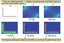
Analogue is a different story, though if you look at wave propagation even at 1kHz the return wants to track the signal quite closely. The lower the frequency the more the return current spreads out (and follows more of the path of least resistance).
Most (probably 99.9%) of digital layouts involve at least 4 layers, one a contigous ground plane. The way signals travel and interact with the return current at digital frequencies requires the use of a ground plane, for signal integrity and EMC control. The return currents follow the path of the signal (path of least inductance), tracking under the routes, thus the use of ground planes (and quite often numerous ground planes, depending on the design requirements. Thus adding the pig tails to digial equipement is not going to add any benefit, and is more likeley to cause problems due to either noise pick up or transmission.
If you want some in depth information, have a look at "electromagnetic compatability engineering" by Henry Ott, chapter 3 covers 'grounds' and appendix d (I think) covers simple diople theory.
Analogue is a different story, though if you look at wave propagation even at 1kHz the return wants to track the signal quite closely. The lower the frequency the more the return current spreads out (and follows more of the path of least resistance).
Adding the pigtails to digital grounds is an EMC nightmare
Got that right Marc! They actually force the loss of sync and the digital source becomes silent. On every forum where these things show up I warn folks not to connect them to a digital ground plane.
Thanks for the insight into frequency and tracking. Do you know if the lowest frequency tracking loss is a chaotic one and what frequency it might start showing up at? Meaning sudden rather than some form of parabola.
Bud
Feelin' a little stoopid here
Bud, I hooked up the RCA version to the analog outputs of three "digital" devices in my system: DAC, CDP, and a Behringer Digital EQ (Feedback Destroyer). I didn't do it to any purely digital input or output. I did get some improvement.
Did I get it right or wrong here? What is your advice on this?
Thanks.
You are fine. The digital grounds will be buffered from the analog portion. So long as you avoid using a balanced connector or an RCA connector that has a direct connection to the digital signal, 1's and 0's rather than waves, you are safe.
Bud
Bud
Hi Bud and all.
Firstly a happy New Year to all
UK site
EMC Information Centre - The EMC Journal (Free in the UK)
US site
EMC Journal portal | EMCJUSA
The latest issue #91 of the EMC journal has an excellent article by Keith Armstrong; "Maxwell's Equations, Quantum Electrodynamics, and good installation practices for SI, PI and EMC". Page 40 has some simulated diagrams of the extent of tracking for various frequencies.
As well as EMC, this is citical to signal integrity for high speed designs and layout, which is where my interest are.
What is interesting for audio signals, is they cover a sort of transition zone, where the low frequency (and generaly the highest power) spread, whereas by 1kHz the signal wants to track to some extent. It would be interesting to have the data for 20Hz to 1kHz in smaller steps.
The "Resistive vs. Inductive Return Current Paths" further complicates things by showing a U shaped trace, where source and load are next to each other! Not done with most practical designs.
This shows the complexity of the audio signals and why inter component (pre-amp to amp etc) grounding is so important. Though on PCB's having a ground plane is better than the star grounds often employed, let the current find its own quite complex path ( a heretical view here😀), though controlling high and low current sections is critical.
When i started doing PCB layout using good ole red and blue tape ups, we would never do an analogue board without ground planes. in those days there were sometimes seperate ground planes connected at a star point. By comparison digital was often a two layer board with the ladder power and ground routing. As components shrunk we then got both analogue and digital on the same board, with again a seperate analogue ground plane and a digital ground plane, again joined at the star point. By the late 90's with the increase in digital, the reduction in supply voltages, and the increasing demands of EMC, one contigous ground plane became the preffered topography, though careful placement and routing is critical (the best way is to start off with two grounds and route everything so digital is over the digital and analogue is over the analogue, then make one contigous plane when layout is finished. Now boards I do have multiple ground planes, one for each signal layer, also miniturisation of components, and the demand for smaller and smaller electronics is making it ever harder to keep the digital mush out of the analogue sections, ferrite beads everywhere.
Now some have gone full circle and some do designs with 'star' grounds (the skinny spider leg ground, that some here prefer, or a multipole antenna) and it is these that report back more improvement than designs with a decent ground plane when using the pig tails.
Have Fun
marc
A few more links:
Printed Circuit Design & Fab Magazine Online
above but more in depth.
http://www.emcs.org/acstrial/newsletters/fall08/tips.pdf
Return Current in Plane
Visible Return Current
Budp regarding the battery use in groundside tweaks: doesn't the attachment of the battery just hang a plane (ie the battery plate) onto the end of the dongle?
Clamping the dongles in the mid point with clamps changes the sound
This may be the same phenom as adding heat shrink in 3 sections. Sonics are tighter.
This may be the same phenom as adding heat shrink in 3 sections. Sonics are tighter.
Curious how a battery is gonna do anything, would be interested in a link to where this is done.
Batteries work by a chemical reaction, so without the other end attached there is not a lot going on.
Batteries work by a chemical reaction, so without the other end attached there is not a lot going on.
Bcharlow: yes I did try it. On my electrostatic panels it de-charged them. I thought they were broken but they charged back up in an hour or so after I removed the 9 volt battery. On everything else it magnfied the groundside effect ... a lot. I left batteries on my sub woofer and mid bass drivers. I took them off my dac output (too much of a good thing as BudP would say).
Last edited:
- Status
- Not open for further replies.
- Home
- Design & Build
- Parts
- Groundside Electrons