I have purchased a dual PCB kit based on the TPS7A4700 regulator:
http://www.diyaudio.com/forums/swap-meet/290138-fs-tps7a4700-low-noise-psu-sale.html#post4696763
As I understand, if I tie the positive out from one PCB to the negative out of the second PCD I will get a dual rail supply.
Want I can't figure out is if the ground created can be connected to chassis ground or whether it becomes a floating ground.
It will be fed from a transformer with dual secondaries, one for each PCB.
It will be used to power an NE5534 buffer between a Raspberry Pi (on board DAC)
BUT....
I will then be switching the source between the Pi buffer and an auxillary XLR input and feeding a balanced input to a class D amp.
I have looked into switching between Balanced and RCA inputs but it requires both signal to be referenced to chassis ground.
So I'm now totally confused as to my ground route from Pi DAC to NE5534 Buffer pre to class D amp
if I tie the positive out from one PCB to the negative out of the second PCD I will get a dual rail supply.
Want I can't figure out is if the ground created can be connected to chassis ground or
whether it becomes a floating ground.
If you are powering each board with its own transformer secondary, so both are independent,
there's no problem at all connecting them in series, minus to plus, to make a bipolar supply.
That connection can be considered the system common, and can also be connected to the chassis,
often through antiparallel high current diodes and/or a parallel low value R and/or a parallel small value C.
The single-point connection to the chassis can help with shielding and/or safety, but is not essential
for the circuit to function.
Last edited:
Phew, thanks for the quick replies...
So as long as the raspberry Pi supply (A single tps7a4700 PCB) and the dual rail based supply as above are connected to chassis ground then I should have no issues with ground loops as everything is referenced to ground including the balanced input of the class D amp?
So as long as the raspberry Pi supply (A single tps7a4700 PCB) and the dual rail based supply as above are connected to chassis ground then I should have no issues with ground loops as everything is referenced to ground including the balanced input of the class D amp?
Phew, thanks for the quick replies...
So as long as the raspberry Pi supply (A single tps7a4700 PCB) and the dual rail based supply
as above are connected to chassis ground then I should have no issues with ground loops as
everything is referenced to ground including the balanced input of the class D amp?
Think more about first connecting the boards together, and then from a single suitable point
on that interconnection, making the chassis connection (with or without diodes/R/C in the path).
A diagram would help. Whether ground loops are formed depends closely on exactly how and where
the various common connections are made. In this case, the chassis can't make a ground loop
if there is only one connection to it, since current only flows between two different points.
Last edited:
Thanks guys,
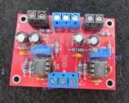
Now I'm trying o find a tranformer that fits in my chassis to power the simple NE5534 pre, pic atached using the tps7a4700 dual pcb board
The size being dependant on current draw, could someone hazard a guess and what sort of power draw is expected of the pre in the pic,
Stu
Now I'm trying o find a tranformer that fits in my chassis to power the simple NE5534 pre, pic atached using the tps7a4700 dual pcb board
The size being dependant on current draw, could someone hazard a guess and what sort of power draw is expected of the pre in the pic,
Stu
Attachments
Darn, thanks for all your help... BUT... just realised I am not center tapping after all!
Will supply each PCB with one of the secondaries, I presume this means that they do not need grounding and that the signal arriving through the preamp board will be the only ground,
sorry for clogging up the forum!
Stu
Will supply each PCB with one of the secondaries, I presume this means that they do not need grounding and that the signal arriving through the preamp board will be the only ground,
sorry for clogging up the forum!
Stu
- Status
- Not open for further replies.
- Home
- Amplifiers
- Power Supplies
- Grounding TPS7A4700 based supply