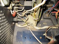
I would start by moving the input GND lead to where R4 or R10 is located and twist together with the input lead (or use coax). This will reduce hum caused by the large loop area at the input.
Post2 saidMany thanks Mark - you get first prize for actually answering the initial question!!!
Every inter-module connection needs two wires.
Keep every two wire connection as a close coupled pair.
Twisted, or coaxial, is slightly better if the size and type of cable suits.
Last edited:
Connect PSU GND and Speaker GND lead to T or 0V. This is probably not the best place to connect them but will work for now.
Let us be clear. The correct way to obtain a ground reference point is to choose a point which is not on the cap junction conductor - and then connect this point using one and only one wire to the cap junction conductor. .
yes there are many physical ways to form a star ground. too bad this is difficult to represent on a schematic.
(maybe use a 0 ohm resistor in few places)
Last edited:
Many thanks Mark - you get first prize for actually answering the initial question!!!
maybe as you understood it😉
for trouble shooting > fix the major hum contributors at their source 1st ( the bulk caps wide connection on a large copper sheet. )
Then look at fixing pick-up on signal level stuff. like Mark Whiteys contribution.
I see the amp schematic has a ground lift resistor included so that should help external loops.
Sadly making a lot of changes at the same time is losing a valuable learning experience.
Last edited:
i remember that in a mark levinson amp, the two toroids are rotated on axis to get the least hum.....
hum can come in two ways, conducted and radiated....
conducted hum has been discussed here to death already...
there is still much room for discussion about radiated hum.....
yes, there is no substitute to learning by taking little steps, and listening to each one for efficacy,
going back or moving forward depending on the outcome...
drawings are mere guides, i seldom follow it as if it was written in stone, but the actual situations will dictate...
hum can come in two ways, conducted and radiated....
conducted hum has been discussed here to death already...
there is still much room for discussion about radiated hum.....
Sadly making a lot of changes at the same time is losing a valuable learning experience.
yes, there is no substitute to learning by taking little steps, and listening to each one for efficacy,
going back or moving forward depending on the outcome...
drawings are mere guides, i seldom follow it as if it was written in stone, but the actual situations will dictate...
yes there are many physical ways to form a star ground. too bad this is difficult to represent on a schematic.
(maybe use a 0 ohm resistor in few places)
having worked as a QC/QA engineer in Oil and Gas projects, contact resistance is one spec we do testing for to make sure all bolted connections are as good as they should be...this is called ducter testing....Contact Resistance Test - Open Electrical
having worked as a QC/QA engineer in Oil and Gas projects, contact resistance is one spec we do testing for to make sure all bolted connections are as food as they should be...this is called ducter testing....Contact Resistance Test - Open Electrical
I always crimp my high current earth connections cos I assumed it was a lower resistance than solder, which is not a great conductor. As long as the connection is tight (gas sealed) there never appears to be any oxidation of the clamped surfaces. Sometimes I solder after crimping, for mechanical integrity ....... what is best?
Sometimes I solder after crimping
i do this all the time....solder ensures connection stays and contacts do not tarnish, but the copper to connector contact must first be there....
Sometimes I solder after crimping, for mechanical integrity ....... what is best?
For high current crimping alone is best.> look at industrial practices. note proper technique and tooling is key.
Soldering after crimping is frowned upon by most technical and safety organizations AFAIK heating it can alter the joints mechanics and soldering by itself has many variables involved. NASA has its own ways.
How many electricians carry a soldering iron or torch on their belt? answer> None
I'm not sure where the origin / beliefs of soldering after crimping comes from. I suspect from the Auto repair/ racing mechanics possibly. some think it must be doubly good. LOL
IF your not sure you have the proper crimping tools and sized lugs. Soldering them after the fact might be prudent.
Last edited:
StunningNot as far to go as you think 😉 Just not happy with the performance yet.
Class A Monoblock Power Amplifier - Product Design Showcase
Sent from my SM-G900W8 using Tapatalk
I'm not sure where the origin / beliefs of soldering after crimping comes from. I suspect from the Auto repair/ racing mechanics possibly. some think it must be doubly good. LOL
IF your not sure you have the proper crimping tools and sized lugs. Soldering them after the fact might be prudent.
yes, proper crimping tools are a must.....
i am not too confident with mine so i solder...
Stunning
Sent from my SM-G900W8 using Tapatalk
yes, i mistook him for Peter Daniels a great diy'er....
his work is unmistakably non newbie.....
I see this statement as vitally important.......................
IF your not sure you have the proper crimping tools and sized lugs. Soldering them after the fact might be prudent.
I don't have a crimp on connector for every cable size I might use.
I don't have a crimper for every crimp on connector I might use.
So, in view of my inadequate crimping practice, I crimp with my cheap crimper using the cheap red/yellow/blue crimp on lugs.
Where they are not insulated, I solder after the poor crimp.
So, in view of my inadequate crimping practice, I crimp with my cheap crimper using the cheap red/yellow/blue crimp on lugs.
Where they are not insulated, I solder after the poor crimp.
Always struggled with those (automotive? coloured crimp terminals). Adhesive lined heatshrink gives a good mechanical bond on non-insulated lugs, and looks good too! Spent the princely sum of £7 on some proper crimping pliers off the bay some time ago - a good investment. You dont want the ones that compress it to an oval shape, they are for the insulated variety, it's the ones where there is a 'w' shaped die.
Electrical Ratchet Crimping Tool Pliers Non-Insulated Terminals / Crimps AT672 | eBay
I am unclear what this has to do with star grounds, as a star ground is not bolted to anything.AJT said:having worked as a QC/QA engineer in Oil and Gas projects, contact resistance is one spec we do testing for to make sure all bolted connections are as good as they should be...this is called ducter testing....Contact Resistance Test - Open Electrical
I have already said that the star point should not be on the reservoir cap junction. Perhaps I should now remind people that the star point should not be bolted to the chassis either. Instead, as for the cap junction, one and only one wire may be taken from the star point to a chassis tag.
But they are for a crimp on that is correctly sized for the cable you intend to use.
The cable must fill the crimp on otherwise the crimping is not as effective as it can/should be.
The cable must fill the crimp on otherwise the crimping is not as effective as it can/should be.
But they are for a crimp on that is correctly sized for the cable you intend to use.
The cable must fill the crimp on otherwise the crimping is not as effective as it can/should be.
I know - confused. Also do not twist the strands before crimping. I would prefer to spend the pennies and minutes getting the correct terminals to match the cables on a project that cost hours / weeks / months / much cash (that is the actual monetary value, not what you tell your partner 🙂)
I am unclear what this has to do with star grounds, as a star ground is not bolted to anything.
I have already said that the star point should not be on the reservoir cap junction. Perhaps I should now remind people that the star point should not be bolted to the chassis either. Instead, as for the cap junction, one and only one wire may be taken from the star point to a chassis tag.
But there has to be a point in the system where multiple cables are coming together, unless everything is on the PCB (doubtful with DIY). How do you suggest they are connected together? Personally I use small a 6mm thick copper plate, insulated from the chassis, with tapped holes for the cable lugs.
Last edited:
The buss bars from the inside of a distribution board are suitable. They can be bought separately, already tapped.
Looks very "professional" in the final product, as does your pic with the green heat shrink sleeving.
Looks very "professional" in the final product, as does your pic with the green heat shrink sleeving.
I am unclear what this has to do with star grounds, as a star ground is not bolted to anything.
I have already said that the star point should not be on the reservoir cap junction. Perhaps I should now remind people that the star point should not be bolted to the chassis either. Instead, as for the cap junction, one and only one wire may be taken from the star point to a chassis tag.
Leach mentions this in his writings....
as a rule, the bolts are used only for fastening, never used as current conductors.....
in the Oil and Gas projects i have been to, ground cables are 16, 35, 70. 120. or 240,mm squared,
terminated using suitable cable lugs and crimping and bolted to grounding buss bars 50 mm x 6 mm thick by as much as 1 meter long.....
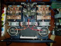
in 1990 i built a super leach amp using ring lugs and bolted to chassis to make a star ground as Leach described.
doing that gave me a very good sounding amp and very quiet too.......
Attachments

- Status
- Not open for further replies.
- Home
- Amplifiers
- Solid State
- Grounding question