have you seen a gremlin?the hum gremlins.
You need to do some basic trouble shooting.
does it hum with no inputs?
does it hum with one stereo pair disconnected from power.
does it hum with signal grounds re-routed.
so on....
someone should do a flow chart
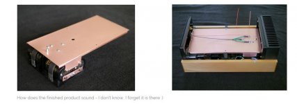
hmm here is an example of single point ground BUT spread over a wide area. uggh
the power caps terminals are mounted far from each other no apparent reason,. All 4 bulk caps are orientated so the common connection was farthest apart.
This is problematical b/c you cannot control the high 120Hz charging currents. E.g hum inducing signals.
IMO rampaging 'mechanical' artistic engineer was left in complete charge of design.
I reckon the OP has altered his test subject in some way from the photos he points to. He should show a snap shot image of the amp open up on the testing area.
Attachments
hmm here is an example of single point ground BUT spread over a wide area. uggh
the power caps terminals are mounted far from each other no apparent reason,. All 4 bulk caps are orientated so the common connection was farthest apart.
This is problematical b/c you cannot control the high 120Hz charging currents. E.g hum inducing signals.
IMO rampaging 'mechanical' artistic engineer was left in complete charge of design.
I reckon the OP has altered his test subject in some way from the photos he points to. He should show a snap shot image of the amp open up on the testing area.
I am here you know 🙂. I had assumed that a thick copper plate would be at the same potential everywhere, rendering component placement less critical. We are all here to learn, rampaging or otherwise. What do you mean 'altered'?
Using a ground plane for reservoir caps is a very good way to lose control of where the currents go, as well as being totally unnecessary. Perhaps a sign that the designer was more interested in visual appeal than electronic performance? A little hum is not surprising.[/QUOTE]
So is the ground plane the reason for the hum? That's all I want to know!
So is the ground plane the reason for the hum? That's all I want to know!
BTW - the reason for using the ground plane was not aesthetic - it was to provide shielding for the amp pcb.
The blog implies no hum was detected if so something has changed from then to now?What do you mean 'altered'?
Oh wow. I have been reading trough the posts here and i am very displeased in the way Andrew T was treated. He is right in his affirmations and his advice should be followed by the OP. He does not need to provide more than he feels he should, he is not here to do the work of the OP, the OP should research the hints received if he does not have the experience necessary.
The blog implies no hum was detected if so something has changed from then to now?
The hum is very, very faint, and not noticed at first (when the blog was written). I have had commercial amplifiers that hum more, but I am a perfectionist 🙂
Originally Posted by AndrewT
Never take your audio ground to the main charging node between the smoothing capacitors ! NEVER !
nope this is completely wrong! the central point between the bulk caps is ground heaven (single point) for audio PAs. If you take it from anywhere else you run the very good risk to have a potential difference or hum signal.
You use nonsense terms like 'audio ground' along with an absolutes! a bit like a bully me thinks, you know all amps don't look like a chip amp PCB. right
so doing what Andrew says you must do, does NOT always work. ahh If life were only so simple.
Last edited:
then AnhdrewT, show us a picture of you completed amp showing how you actually did your amp,,,if you want to help newbies, pictures will help immensely...
talk is cheap, only an acutal amp will show for sure....
thank you my sentiments exactly!
how do you show a single point placed somewhere on a ground plane on a schematic?
perhaps DF69 has the way
youll always be surprised by what the designers comeup with in real life , some guidelines please.
I shake my head when I see ground planes on power supplies or audio PAs.
Last edited:
I am here you know 🙂. I had assumed that a thick copper plate would be at the same potential everywhere, rendering component placement less critical. We are all here to learn, rampaging or otherwise. What do you mean 'altered'?
I would suggest putting cuts or slices the copper plate but that weakens mechanical structure. got plexiglass?
perhaps disconnecting the bulk caps from the ground plane and use wiring, perhaps rotating the caps so they all face each other would be ideal & quickest for testing I reckon.
Use a central ground scheme like AJT suggested on his posted drawing.
I suspect Andrew new guidelines are for chip amps with PCB ground planes which shifts the central ground heaven to the PCB bypass caps. This is a very rare case.
I bet none of his amps are built like what he demands others! LOL
Last edited:
Perfectionist or not, all high end amplifier must be completely silent.😀The hum is very, very faint, and not noticed at first (when the blog was written). I have had commercial amplifiers that hum more, but I am a perfectionist 🙂
Maybe it is not a ground problem!
Maybe would be interesting to know what type of power supply is used for the amplifier and the problem is at this level!
Perfectionist or not, all high end amplifier must be completely silent.😀
Maybe it is not a ground problem!
This was what I was hinting at when I suggested he spread the amp out on a workbench and try to make it silent there first.
Thanks for all the input - lots of thing to try over the next few weeks. There is another possibility, the low voltage supply uses a PCB mounted transformer feeding a Ben Duncan inspired LM317 / 337 regulator stage. I have had trouble with that make of transformer before so will have another look at that also.
It's such a shame that so much contradictory advice has left you with many different solutions.
Post23 in part agrees.
Look at post44. That is being made by an EE professional.
He at least sees the sense in what I have recommended.
There are others that agree, but they have not posted here, yet.
Post23 in part agrees.
Look at post44. That is being made by an EE professional.
He at least sees the sense in what I have recommended.
There are others that agree, but they have not posted here, yet.
Last edited:
When it comes to grounding correct drawing is vital, as correct drawing can led to correct implementation. It may be that all the bad grounding done by newbies (and others) comes from taking bad drawings too literally.
yes, in the drawings conductors can show as straight lines, but in real life they can curve and be snakey.....
in my years of building actual amps, i found that returning the speaker returns to the psu ground has the biggest impact when it comes to stability and noise....
the invention of the main audio ground came a much later when i have built many amps that were quiet......to me it does not make any more sense....i do not need it...i may already been doing it when they came up with the idea...
thank you my sentiments exactly!
how do you show a single point placed somewhere on a ground plane on a schematic?
perhaps DF69 has the way
youll always be surprised by what the designers come up with in real life , some guidelines please.
I shake my head when I see ground planes on power supplies or audio PAs.
i have always admired the work of Peter Daniel, you can see pictures that are real nice and well made and easily pick up ideas from his photos....
there are others like Ostripper, Apex, Miles Prower, they have demonstrated competence and willingness to help others....
that is why i do not seriously take people who likes to talk and harass newbies but can not show anything, no pictures, just words......
Hi number7, I would start by moving the input GND lead to where R4 or R10 is located and twist together with the input lead (or use coax). This will reduce hum caused by the large loop area at the input.
Connect PSU GND and Speaker GND lead to T or 0V. This is probably not the best place to connect them but will work for now.
Connect PSU GND and Speaker GND lead to T or 0V. This is probably not the best place to connect them but will work for now.
Let us be clear. The correct way to obtain a ground reference point is to choose a point which is not on the cap junction conductor - and then connect this point using one and only one wire to the cap junction conductor. The aim is to have one and only one connection to the cap junction. You don't reference the circuit to the caps; you reference the caps to the circuit.infinia said:nope this is completely wrong! the central point between the bulk caps is ground heaven (single point) for audio PAs. If you take it from anywhere else you run the very good risk to have a potential difference or hum signal.
I said as much in a previous post, but it seems to have disappeared. Number7 quotes from it in his post 44, so it must have appeared for a while!
Ground planes have no role in this. Fine for RF and some digital, but inappropriate for analogue audio.
post4 is wrong. Pavouk.org got it completely wrong and AJT should never have copied it. He has been told before and chooses to post this erroneous layout yet again.
Never take your audio ground to the main charging node between the smoothing capacitors ! NEVER !
I think I must agree. There is a ground connection from the input RCA to the board. There is also a ground connection at the output side. I don't know this particular board but I assume that on the bard the input- and output grounds are interconnected as a signal ground, and that this is returned to the star with the wire shown on the output side.
By additionally connecting the input ground to the star you create a ground loop.
What you really want is on the board a signal reference ground that starts with the input RCA ground all the way to the output, and that does not carry any power return currents.
Jan
Last edited:
Hi number7, I would start by moving the input GND lead to where R4 or R10 is located and twist together with the input lead (or use coax). This will reduce hum caused by the large loop area at the input.
Connect PSU GND and Speaker GND lead to T or 0V. This is probably not the best place to connect them but will work for now.
Many thanks Mark - you get first prize for actually answering the initial question!!!
- Status
- Not open for further replies.
- Home
- Amplifiers
- Solid State
- Grounding question