C
CryingDragon
Ok i have my PCB layed out and am getting ready to etch but i need to know of my grounding is proper.
I have all but #1 ground connected on the schematic below,Where should i put the speaker return ground? Tie it to VCC-?? I don't want a ground loop going back into the input.
Also is my grounding right? Should all but #1 and #6 be connected? Or should i take # 7 and 8 off the signal ground point and connect them to VCC- as well?
Attachments
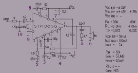
The grounding for best results should be:
4,3,2,7,8 should already be a common point
9, 10 should already be a common point
5,6 should already be a common point
Then connect these three grounds together at a common single-point "star-connection". The point that you have labelled 1 on the diagram is -VCC and is your negative supply rail and is NOT connected to ground.
Does everyone else agree with this solution or does anyone else have any other suggestions?
BeanZ
C
CryingDragon
one more ?. ok so i am connecting
9 and 10
5 and 6
4 3 2 7 and 8
I am connecting them by the numbers you say on the PCB (IE 9 and 10 are connected by traces but no connected to any other numbers like 5 or 6) now Do i tap these all (once i get the PCB made and put vias in the traces) and bring them off the card (wires) and connect them all at one binding post thats not connected to anything else?
4 and 7 are high current grounds and must be run back to the transformer center tap by themselves. 1 is -42V, not ground. The 4.7µF input cap and the 47µF feedback cap should both be non-polar types and have a 0.1µF film type soldered in parallel with them.
down to earth
I'd mostly agree with Beanz. However, I would connect 9,10 and 2 together on the pcb. This is because the gnd for the feedback needs to be the same voltage as the ground for the input or else there will be an error in the subtraction. 1 is -Vcc and should NOT be connected to ground.
In summary:
2,9,10 connected together on the pcb
3,4,8,7 connected on the pcb
5,6 connected on the pcb
As Beanz says, you then need 3 separate ground lines back to a star point (usually at the psu where the smooting caps connect). Purists might have 3,8 and 4,7 with separate wires back to the star point but this is not strictly necessary.
As for capacitors, I believe it is ok to use electrolytics as show in the schematic. This is because the Sanyo chip has pnp bipolar transistors on its inputs. These will draw a small bias current from their bases and these currents will create a small voltage drop across the input resistor and the feedback resistor, thus biasing the electrolytics adequately. This is common practice for bipolar inputs.
BAM
TraderBam may be correct. If ground 2 is part of the signal circuitry then in needs to be connected to 9 and 10. What you are trying to do is keep the power supply grounds, small signal grounds, and large signal grounds currents separated but maintained at the same voltage level. The lines which are tied together should be very low impedance which means the use of ground planes. Just smear the copper over a wider area and keep the traces as wide and as short as possible. The voltages are keep at the voltage by connecting them to the same point at a star ground. The voltage that they are maintained at is...the earth. The earth becomes the reference. If you connect the grounds with long lines or start connecting lines into the trace as it travels to the star point, there will be noise. What happens is that the current will find a lower impedance path to ground...usually through the circuitry...this is what causes the noise. The theory is to maintain a straight, direct, short, low impedance ground to a fixed reference. By doing this, you ensure that your traces are the abolute shortest path to ground. A technique you may want to try is to put small resistors between the grounds so that the ground and return currents are forced to stay in their own lines. If you maintain the above criteria for routing, then you will probably not need the resistors.
BeanZ
BeanZ
Silent grounds
My only doubt is in whether joining the 10/9 grounds with 2. Many designs suggest using a 10 ohms resistor between input and feedback grounds, but they say to use it only on one channel.
BeanZ suggestion, of providing resistors on the pcb for interconnecting these ground groups is quite good. Maybe provide pads that you can test using resistors or jumpers, and see what sounds better.
An important thing is where to put that star point, which many place between the large supply capacitors and seems to be the wrong point.
We may spends hours and hours discussing ways to ground best, but as long as we ourselves tell what we found on our own setup we will still be discussing theory.
Carlos
C
CryingDragon
Wow thanks for all the responses,sorry i keep asking just beginner questions but this is my first DIY i've only worked with such things as 555's and such in the past. I don't need absoloute perfect sound just reletively clear,I've gotten many diffrent ideas,Witch would be best do you think? And do i or do i not connect the star ground to the - on the PSU caps?
The power supply cap common will attatch to the star ground point. Also think about bleeder resistors on those caps to discharge them after power-down.
BeanZ
BeanZ
C
CryingDragon
Mkkaaaay
I have
2,9,10 connected together on the pcb
3,4,8,7 connected togehter on the pcb
5,6 connected together on the pcb
Now i have pads to tap these all so lemme see if i have this right:
I take all the taps (wires) and connect them and the ground (CT off the xformer) of the psu caps together?
like this??
Attachments
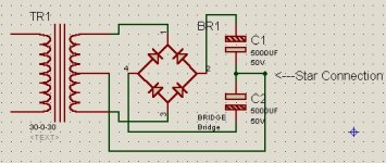
Looks like you've cracked it, CD. The star point needs to be at the point where C1 and C2 connect - not on a spur from this point. Make sure all the ground "taps" connect at as much of a single point as possible. There are lots of ways to do this. When I make a star ground I usually solder eyelets on each wire and then screw them together on a bolt and I put the high current gounds at one end of the stack and the low current at the other end. Try to run the ground wires and psu wires in a close bunch from psu to pca to reduce loop inductance.
BAM
(ps: your bridge rectifier isn't connected correctly in the diagram )
)
BAM
(ps: your bridge rectifier isn't connected correctly in the diagram
)
C
CryingDragon
YEAYY!!!!
I got it...yeay! Umm...hehe Ja sueualy i don't go with 1 2 3 and 4 on bridges i go with the markings on the chip 😀 Anyway...this is sweet,Thanks alot,you guys are my lifeline on this. Without you it would be just a big puff of smoke.
I got it...yeay! Umm...hehe Ja sueualy i don't go with 1 2 3 and 4 on bridges i go with the markings on the chip 😀 Anyway...this is sweet,Thanks alot,you guys are my lifeline on this. Without you it would be just a big puff of smoke.
traderbam said:The star point needs to be at the point where C1 and C2 connect - not on a spur from this point.
That is opposite of what I do. If the caps are mounted on PCB's I run a heavy, short trace for the common connection between the caps and then run a short stub off the middle of that trace to my star ground point.
If the caps are connected with harnesses then I run a heavy gauge wire between the common connections of the caps and run a single wire from one of the common cap terminals to the star ground.
Making the ground connection that way means the capacitor currents aren't flowing through the star ground point.
What is the advantage to how you recommend doing this?
Phil
Meeting point
>The star point needs to be at the point where C1 and C2 connect - not on a spur from this point.
That's something you shouldn't do apparently: put capacitors meeting point and star point on the same place. The star needs to be away from it. Reasons for this seem to be that is a high current point.
Doug Self seems to give similar reasons from where you should pick the feedback on an amp output, and that you shouldn't do it from the point where the two emitter resistors meet, but slightly away from it.
The star should also be isolated from the external box, though a wire from it should also go to the star.
Carlos
C
CryingDragon
My exteral box is gonna be plastic witha tin top (those "project boxes") from radio shack,i know it sounds silly but you'll see when i'm done it's gonna look badass. 😉 I'm also gonna be using a silver P3 and 4 cooler heatsink for each chip and the sinks also will have fans on them
Those plastic cases will melt. They are made of polycarbonate or polystyrene. They have a low melting temp. The carbonate higher than the styrene. If there is a heatsink it will be undesirable.
BeanZ
BeanZ
Star point
"Doug Self seems to give similar reasons from where you should pick the feedback on an amp output, and that you shouldn't do it from the point where the two emitter resistors meet, but slightly away from it. "
This is to do with taking the feedback from a true summing point (i.e. the summed output to the speakers) and is a valid point.
The problem is, with a single transformer secondary, the bus-bar between the caps is not a summing point, and the significant and large current flows here make for measurably different potentials (DC and AC) as you move along it.
Connecting at a tap though, gives you a shared current path, of finite impedance.
I REALLY like BAM's idea - it allows lots of wires, in the smallest possible distribution, with the end result being a 'lump' of commendable volume, and hence low impedance.
With dual centre-tapped secondaries, the bulk of the current flow can be removed from the bus-bar, improving performance considerably, by removing the current flow from the signal earth (with correct wiring).
Remeber the current flows in loops - that's really important.
A.
Finding a point
"This is to do with taking the feedback from a true summing point (i.e. the summed output to the speakers) and is a valid point."
Just mentioned this to illustrate that the right point is not always the most logical.
"Connecting at a tap though, gives you a shared current path, of finite impedance."
I wonder if you can use a T shaped pcb track, the two opposite ends being the caps and the lone end the star.
"I REALLY like BAM's idea - it allows lots of wires, in the smallest possible distribution, with the end result being a 'lump' of commendable volume, and hence low impedance. "
I have seen using the caps meeting point used as star on many projects... and criticized later on.
What I don't know is how potentials work when you use a "surface" instead of a track. That is many use a copper surface or even a metal plate and put the star there.
"With dual centre-tapped secondaries, the bulk of the current flow can be removed from the bus-bar, improving performance considerably, by removing the current flow from the signal earth (with correct wiring)."
Yes, that seems to be the way many transformers are being rectified now, and I should be trying it on my next project. But you need separate secondaries.
"Remember the current flows in loops - that's really important."
But how does that concept apply on why we shouldn't use the caps meeting point? We are not making a loop here.
Carlos
- Status
- Not open for further replies.
- Home
- Amplifiers
- Solid State
- grounding help.