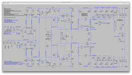
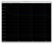
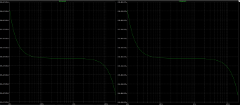
Take a look at the noise contributions from the active parts in the ltp front end.
I left out the current sources because they were so far down compared to the rest, they are really not the main source of noise in the front end (no need to filter their tail 100k).
The 4 biggest contributors are in the 2 current mirrors, with the one on the positive side a little more. Why? Go figure.
The next 2 are the ones connected to the input. The opposite ones getting the feedback signal contribute a little less and they don't have that sharp rise at the low end.
Interesting isn't it?
I think perhaps we can clean up the current mirrors.
Attachments

Take a look at the noise contributions from the active parts in the ltp front end.
{cut}
The 4 biggest contributors are in the 2 current mirrors, with the one on the positive side a little more. Why? Go figure.
The next 2 are the ones connected to the input. The opposite ones getting the feedback signal contribute a little less and they don't have that sharp rise at the low end.
Interesting isn't it?
{cut}
....
{M. Moderator, kindly permit me to post edited quote, despite Rule 18}
Oh, yes, very interesting. This revelation that the current mirrors contribute significant noise is counterintuitive to me, but by chance this very topic is under discussion here - it confirms your finding:
http://www.diyaudio.com/forums/solid-state/171159-bob-cordells-power-amplifier-book-188.html
My reaction is to increase the emitter resistors on the current mirror transistors to say 100-220 ohms to obtain a significant reduction in noise. Read that discussion and tell me what you think. We'll have to tweak the VAS to compensate for this to make sure that is still in the right range.
You also point out that the input side of the differential pairs seems to contribute more noise than the NFB side. Could that be distortion from the input capacitor, with the LF rise? Note that I reduced the the 2.2k input resistor to 1k to reduce noise, but for other reasons I doubled the input and feedback resistors.
The Cordell discussion sheds light on other noise contributors in the input stage too, even the humble input resistors. Those gurus tease fine points I did not even know existed, which I sometimes find {deleted}, but this is extremely relevant.
I've been concerned that the RC filter on power to the input section may need improvement too. I suspect it will pass low frequency noise from the VAS stage, so perhaps another RC stage is needed, something simple but effective. What do your simulations suggest on that topic?
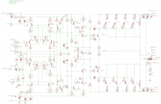
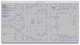
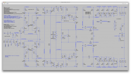
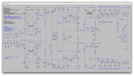
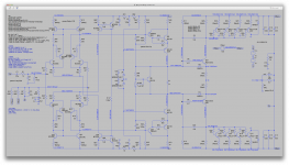
I'm attaching a schematic that includes Szlikai LTP, doubling of feedback and input resistors, larger CM emitter resistors, and added RC filter. I hesitated to add the Szlikai pair, but we need to know if this is a win or not. The RC is experimental, does it help?
Attachments
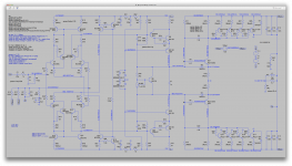
The vas base resistors didn't require changing from 22k, leaving the load res at 47.
And actually the 39k feedback res on the driver bases could've stayed as well.
I changed them to 33k, but there was no differences that I could see, aside from adjusting bias a little.
I looked at thd at 20hz, 200, 1k, 5k, 10k and 20k. We can see it does rise a little at 20k, but not too much, which isn't bad, and it's actually rising much more at the low end, and the solution to that was as I showed earlier, by increasing the cap values a bunch. This can cut that thd in half at 20hz.
Noise got better, and we can see the bulk of it appears below about 10hz.
I'll poked around for the contributions.
Intuitively, I would think raising the res values on the mirrors would also raise noise, because higher values with the same current would create more johnson noise. I'll look at this...
Attachments
-
 Screen Shot 2016-12-12 at 12.28.40 PM.png676.6 KB · Views: 65
 -
 Screen Shot 2016-12-12 at 12.28.02 PM.png9.8 KB · Views: 59
 -
 Screen Shot 2016-12-12 at 12.27.42 PM.png243.3 KB · Views: 54
 -
 Screen Shot 2016-12-12 at 12.23.41 PM.png46.5 KB · Views: 56
 -
 Screen Shot 2016-12-12 at 12.23.06 PM.png48.4 KB · Views: 47
 -
 Screen Shot 2016-12-12 at 12.22.34 PM.png46.5 KB · Views: 61
 -
 Screen Shot 2016-12-12 at 12.22.04 PM.png47.2 KB · Views: 58
 -
 Screen Shot 2016-12-12 at 12.21.33 PM.png47.3 KB · Views: 64
 -
 Screen Shot 2016-12-12 at 12.20.49 PM.png204.4 KB · Views: 86
 -
 Screen Shot 2016-12-12 at 12.20.32 PM.png44.8 KB · Views: 103
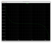
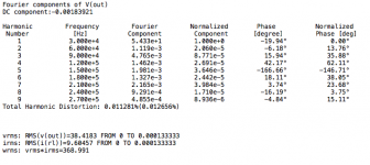
I cut out below 10hz the noise figure, where it very sharply rises. I think this is hard to lower there below 10hz. Not sure how.
We can perhaps gain a little bit more and get the SNR a little better. Seems we're at a little less than 90db.
We can see the big contributors are not as far ahead of the others as before.
I didn't look previously at the noise in the resistors, so at the moment I can't tell if raising the degen res on the mirrors increased or decreased noise. But the noise contrib from the mirrors' active parts has dropped. Perhaps the drop in the actives has been more than the rise in the passive...
We can also see the sziklai stuff is definitely not a big source of noise, and the noise in the base stoppers is very low.
Attachments
-
 Screen Shot 2016-12-12 at 12.42.43 PM.png217.5 KB · Views: 55
 -
 Screen Shot 2016-12-12 at 12.43.11 PM.png219.8 KB · Views: 64
 -
 Screen Shot 2016-12-12 at 12.43.34 PM.png219.5 KB · Views: 70
 -
 Screen Shot 2016-12-12 at 12.44.05 PM.png217.9 KB · Views: 62
 -
 Screen Shot 2016-12-12 at 12.42.18 PM.png234.4 KB · Views: 65
 -
 Screen Shot 2016-12-12 at 12.41.35 PM.png209.8 KB · Views: 57
 -
 Screen Shot 2016-12-12 at 12.41.07 PM.png203.1 KB · Views: 56
 -
 Screen Shot 2016-12-12 at 12.40.22 PM.png214.2 KB · Views: 64
 -
 Screen Shot 2016-12-12 at 12.44.57 PM.png202.2 KB · Views: 59
 -
 Screen Shot 2016-12-12 at 12.44.30 PM.png676.8 KB · Views: 54
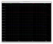
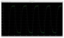
I wondered how the slew rate had evolved with the raise in value of the degen res in the mirrors.
And indeed it has apparently been reduced at close to 20V/us.
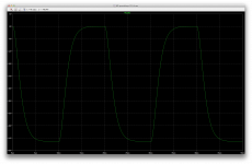
Everything still looked pretty good with sine waves, however the square waves reveal that some oscillations have reappeared. That's a bugger.
And indeed it has apparently been reduced at close to 20V/us.
Everything still looked pretty good with sine waves, however the square waves reveal that some oscillations have reappeared. That's a bugger.
Attachments


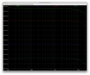
A simple reduction from 56p to 47p of the global feedback comp cap stops those oscillations on the squares.
It likely has other implications, not only thd, which with a lower value usually thd goes down, but things like phase and gain margin are affected. However at this point, I'm not even certain what they really are.
It likely has other implications, not only thd, which with a lower value usually thd goes down, but things like phase and gain margin are affected. However at this point, I'm not even certain what they really are.
Attachments
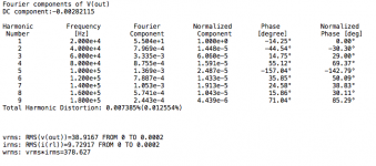
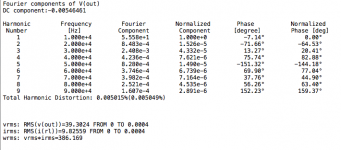
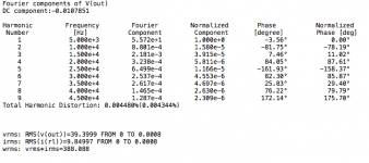
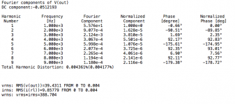
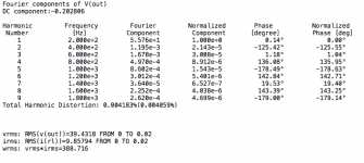
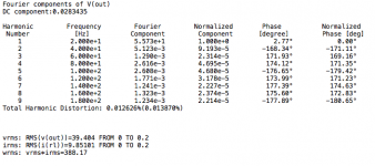
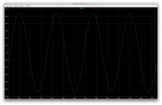
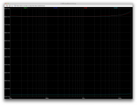
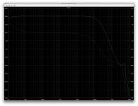
I was just curious about thd at 30khz, and if oscillations could be seen there.
So here it is.
Not too bad.
So here it is.
Not too bad.
Attachments
http://www.diyaudio.com/forums/solid-state/171159-bob-cordells-power-amplifier-book-188.htmlbut by chance this very topic is under discussion here - it confirms your finding:
http://www.diyaudio.com/forums/solid-state/171159-bob-cordells-power-amplifier-book-188.html
That is a very long thread and I have been reading it off and on, but not all of it.
I'm not in the best receptive condition to be able to read that much stuff in any reasonable amount of time. Although I have beed reading his book, I'm far from done and I can only read it a small amount at a time. It'll take me time to fo through that much data. (not just age. medical conditions limit me)
Could you point directly to the part of that thread where the most relevant stuff is being discussed?
You also point out that the input side of the differential pairs seems to contribute more noise than the NFB side. Could that be distortion from the input capacitor, with the LF rise? Note that I reduced the the 2.2k input resistor to 1k to reduce noise, but for other reasons I doubled the input and feedback resistors.
Since the latest changes, the difference has lowered. But it's still there.
And I noticed that although the larger contributions came more from the positive side earlier, that has now been reversed. But the difference is so small, maybe it's just influenced by some offset, and changing that offset a little can swing the difference the other way?!?
The Cordell discussion sheds light on other noise contributors in the input stage too, even the humble input resistors. Those gurus tease fine points I did not even know existed, which I sometimes find {deleted}, but this is extremely relevant.
If you point us to the post numbers range where this is discussed, we can find it more easily. With such a lengthy thread, it's a needle in the proverbial haystack.
I've been concerned that the RC filter on power to the input section may need improvement too. I suspect it will pass low frequency noise from the VAS stage, so perhaps another RC stage is needed, something simple but effective. What do your simulations suggest on that topic?
I'm sorry but you lost me there. What RC filter are you referring to?
and added RC filter.
Is this the extra one to clean up the low voltage rails? Is that what you're referring to above?
I think the cleaner the better, and I suspect any such improvement would be beneficial.
I can try with and without to compare this.
I hesitated to add the Szlikai pair, but we need to know if this is a win or not. The RC is experimental, does it help?
Adding the sziklai doesn't seem to have any adverse effect so far. Not certain yet what they do bring though. If they increase the gain and improve linearity, this should provide more open loop gain and lower thd. Perhaps it's what we see so far with a thd that is rather reasonably low even at 30khz.
The thd at the low end seems more problematic. It's unusually high compared to the high end when we compare how other more "conventional" topos are used.
I'll compare the effect of the extra filtering on the low rails now.
Turns out, adding an extra RC filter on the low rails doesn't bring anything at all.
On the left screen shot it's there, and without on the right.
No real difference.
I thought it would be a little better at least. No such luck.
On the left screen shot it's there, and without on the right.
No real difference.
I thought it would be a little better at least. No such luck.
Attachments
Continuing the comparison on the noise figures.
The current sources are nothing to worry about, as they're really not the major contributors.
What does puzzle me is the rather large difference between the positive and negative side for their contributions.
The current sources are nothing to worry about, as they're really not the major contributors.
What does puzzle me is the rather large difference between the positive and negative side for their contributions.
Attachments
I'm still looking in now and again... and don't want it to sound like I'm heckling from the side-lines 🙂
Rails in LT don't need any decoupling because the voltage source and connections are 'perfect' having zero impedance. Its sometimes worth adding a little series impedance to the rails to see how that affects things.
Always be suspicious of small changes that seem to fix an issue such as changing the value of a cap by a few pf. That suggests a very marginal and probably totally different behaving design for when you get to build a prototype.
I'm still looking in now and again... and don't want it to sound like I'm heckling from the side-lines 🙂
Not at all, you're very welcome of course. Please barge in at any time.
Rails in LT don't need any decoupling because the voltage source and connections are 'perfect' having zero impedance. Its sometimes worth adding a little series impedance to the rails to see how that affects things.
Quite right. I tend to forget how the simulations have some aspects a little to ideal.
I can add some series resistance to that supply and re-test the 2 situations. With some impedance, the vas might induce a little something that the extra filter might catch.
Always be suspicious of small changes that seem to fix an issue such as changing the value of a cap by a few pf. That suggests a very marginal and probably totally different behaving design for when you get to build a prototype.
You must be thinking of the global comp cap that I reduced to 47p from 56p.
Hopefully this will work out fine. It's a compromise.
But when I can see what the phase and gain margin actually really are, we may have to revise the compensation a bit to get what we need.
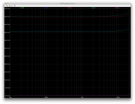
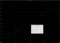
Since the recent changes, I hadn't looked at the ac analysis, so here's one.
And I added a series resistance to the 15V low rail supplies, at first I added 0.25ohms, but then went to 1ohm.
It doesn't affect noise. This is more a question of ripples, induced by the vas...
Doesn't bother anything. What kind of series impedance can we expect from the regulators anyway?
Perhaps there is one thing that could be added on the "clean" side of the low rails, a 100n decoupling, in addition to the larger caps.
We do have a little gain spike in the ac analysis, but way below the unity gain, and pretty high up there, so it can't bother us.
On a real build, it might be a good thing to add 100n decoupling caps, on each power device, close to their emitter resistors.
One other thing we might try later if need be when looking closer at compensation and phase/gain margins, is to split the zobel and have it on each side of the output coil. (a PI config)
Attachments

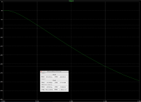
CM Noise changes with emitter resistor values
Spookydd said:
That is a very long thread and I have been reading it off and on, but not all of it.
I'm not in the best receptive condition to be able to read that much stuff in any reasonable amount of time. Although I have beed reading his book, I'm far from done and I can only read it a small amount at a time. It'll take me time to go through that much data. (not just age. medical conditions limit me)
Could you point directly to the part of that thread where the most relevant stuff is being discussed?
+++++++++++++++++
I say: Sorry, I thought my bookmark put you on it, it does for me but that could be a browser history effect. It is a long thread, I read it backward and stumbled on Post 7489.Anyway, there was a graph, and I picked a higher resistor value of 100 ohms because it looked close to the best, and would not upset other sections much. Here is the post 7489 by Mark Johnson:
This thread is amusing, because we have experts discussing such miniscule points and a little bit of rivalry too. All to the good, since this is precisely what we were studying.
On another topic, you say we picked up tiny oscillations, that is a concern. One area in which I did not add base stoppers is the CM, and I did consider it. Maybe that is the source of this new oscillation? Something to consider.
The graph:
Spookydd said:
That is a very long thread and I have been reading it off and on, but not all of it.
I'm not in the best receptive condition to be able to read that much stuff in any reasonable amount of time. Although I have beed reading his book, I'm far from done and I can only read it a small amount at a time. It'll take me time to go through that much data. (not just age. medical conditions limit me)
Could you point directly to the part of that thread where the most relevant stuff is being discussed?
+++++++++++++++++
I say: Sorry, I thought my bookmark put you on it, it does for me but that could be a browser history effect. It is a long thread, I read it backward and stumbled on Post 7489.Anyway, there was a graph, and I picked a higher resistor value of 100 ohms because it looked close to the best, and would not upset other sections much. Here is the post 7489 by Mark Johnson:
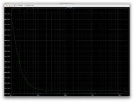
Originally Posted by jan.didden View Post
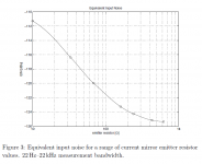
{Jan Didden} Bob, I don't understand this - I would have thought that the mirror degeneration resistor might be too high for low noise?
{Mark Johnson} Jan, take a look at Samuel Groner's critique of D.Self's 5th edition, page 4, Figure 3. Groner built several "model amplifiers" (all TO92 IPS + VAS + classA_EF_OPS) and measured their equivalent input noise with different values of emitter degeneration resistors in the current mirror. What he found in real life, exactly matches what you and I see in LTSPICE ".NOISE" simulations: bigger degeneration resistances in the mirror, give lower noise. Groner realized that measured data on real amplifiers would be a LOT more convincing than simulations or equations, and that's what he did.
This forced Self to add a couple of paragraphs to the 6th edition, not quite admitting that he made a design error, but instead marvelling over this discovery of a new noise source (6th edition p.152).
This thread is amusing, because we have experts discussing such miniscule points and a little bit of rivalry too. All to the good, since this is precisely what we were studying.
On another topic, you say we picked up tiny oscillations, that is a concern. One area in which I did not add base stoppers is the CM, and I did consider it. Maybe that is the source of this new oscillation? Something to consider.
The graph:
Attachments
I say: Sorry, I thought my bookmark put you on it, it does for me but that could be a browser history effect.
It was taking me right to the latest of the thread, and your configuration may also display a different number of posts per page, so the link doesn't take me where you intended it to. No biggie...
It is a long thread, I read it backward and stumbled on Post 7489.Anyway, there was a graph, and I picked a higher resistor value of 100 ohms because it looked close to the best, and would not upset other sections much. Here is the post 7489 by Mark Johnson:
Yes, very interesting. Cool stuff. We learn from the best.
This thread is amusing, because we have experts discussing such miniscule points and a little bit of rivalry too. All to the good, since this is precisely what we were studying.
Good timing. And this is friendly rivalry. All good. I can only advance the knowledge.
On another topic, you say we picked up tiny oscillations, that is a concern. One area in which I did not add base stoppers is the CM, and I did consider it. Maybe that is the source of this new oscillation? Something to consider.
My hunch is that the recent changes have altered certain things that may have moved some pole or something like that, and compensation was no longer quite matching the needs.
As you noticed, a simple slight reduction of the global comp cap did the trick, and at the same time, a lower value there also reduces thd.
I wouldn't worry too much about that, with the adjusted comp, we're all good again.
Remains to be seen the actual phase/gain margins, and that's where things might get tricky. If we have enough of both now, then all is well, but if we're short on something, then more adjustments would be needed to get what's missing, and that would change again some things like thd and perhaps even noise depending on what we adjust.
In any case, we need a stable amp, and keep it as easy as possible to build by diyers. I think it's looking good now.
spookydd said:
On a real build, it might be a good thing to add 100n decoupling caps, on each power device, close to their emitter resistors.
+++++++
I will put HF bypass caps on electrolytic caps that filter power later on, but they clutter up the schematic and I did not think they affect the model, so I would add them last. They are essentially free, since I surface mount them bottom side. We can easily bypass the output devices too if that has merit. Make a list and we can add explicit bypasses.
For any layout, I assume we have a ground fill one side. I'm not sure if this can be modeled, but I'm convinced it minimizes noise, both by reducing impedance and reducing crosstalk. In my professional work I always used power and ground planes on 4-6 layer boards, but I suspect that is overkill for audio and too costly also. A ground fill is almost as good as a ground plane for no cost.
I will put HF bypass caps on electrolytic caps that filter power later on, but they clutter up the schematic and I did not think they affect the model, so I would add them last.
Right. That's what I meant. We don't need them in our simulations, they wouldn't do anything there, we don't have anything bringing in hf or whatever.
It was just a reminder to include them in a real build.
And adding a 100n maybe on the ltp supply lines might also be a good idea.
They are essentially free, since I surface mount them bottom side.
Oh boy! SMT! That is one thing I can't touch. If I had to use SMT on any of my builds, I would have to let someone else handle the soldering. I can't touch that. Too damn small.
We can easily bypass the output devices too if that has merit. Make a list and we can add explicit bypasses.
Well, this one was the first to start the list. More likely to add as we think about them.
For any layout, I assume we have a ground fill one side.
I surely would do that systematically. I would consider double sided as the minimum, so a ground plane can be used and definitely avoid any straps. Single sided is almost certain to demand using straps, even with the best layout.
I'm not sure if this can be modeled,
I doubt it. Not to my knowledge.
but I'm convinced it minimizes noise, both by reducing impedance and reducing crosstalk.
Indeed! Why not do it? Since I doubt having single pcb made is that much cheaper than double sided anyway.
In my professional work I always used power and ground planes on 4-6 layer boards, but I suspect that is overkill for audio and too costly also. A ground fill is almost as good as a ground plane for no cost.
Overkill for sure. Double sided with a ground plane is good. And one thing to remember for audio amps is to have the thickest copper possible.
Little things to keep a checklist on...
I've been reading some more "self" about noise. Especially the part cited in that discussion about the "cordell" book.
I'm not ready to read the whole book in one shot, not even close, but at least once in a while when the situation arises, I read different parts.
There is one thing I knew, which is the while we thrive to reduce noise by increasing the mirror degen resistors, at the same time this reduces slew rate.
And I wanted a closer look at the slew rate. Better than that quick look from earlier, where I only took it as is from the square signal with normal drive level.
This time I drove it very hard into clipping, to get the steepest rise and fall we can get. By the way, we have no signs of oscillations, even driven hard at 10V on the input.
It turns out that we haven't reduced the slew rate too much, and what we have left is quite respectable I think. And furthermore, both rising and falling rates are very close to each other, so we have a rather symmetric functioning amp. I think this is simply due to our use of the fully symmetric topo. This is good.
We have a rising rate at close to 29V/us, and the falling rate is close to 28V/us.
Pretty damn close to symmetric don't you think?
Now, can we live with the current noise situation? It's not bad, but can we improve it without taking away something else?
Self even brings up one possible thing to do to improve the noise figure in the input devices, by paralleling them. But now that we have a sziklai pair on top of that, I think that would be going a little too far. And to gain 3 to 6db, it may not be worth even thinking about it. The extra complexity would be rather serious.
Attachments
I just tested something that is to note when selecting parts before building.
The 2 balancing 100k resistors must be matched as closely as possible to obtain the best rail centering.
Assuming those resistors are chosen as 1% tolerance and in a worst case scenario when one is 1% above while the other is 1% below its nominal value, the rail offset can drift by nearly 500mV.
In the simulation, having the exact same value allows a very close centering at much less than 1mV offset.
The tiny imbalance in the simulation isn't due to those balancing resistors but rather to the differences between the active parts' models. Having gain and feedback brings this to a very nice balance, but if the balancing resistors aren't properly matched, that can really cause an offset.
This is just as true for the ltp and CM/CS devices, along with all their associated resistors, degen, etc...
So among the important things to note in a checklist for building, is to try to match as many of those parts as possible.
I just tested something that is to note when selecting parts before building.
The 2 balancing 100k resistors must be matched as closely as possible to obtain the best rail centering.
Here in Germany resistors with 0.1% tolerance are easily achievable, but not too cheap, though. Otherwise - what about a trimpot?
Assuming those resistors are chosen as 1% tolerance and in a worst case scenario when one is 1% above while the other is 1% below its nominal value, the rail offset can drift by nearly 500mV.
Doesn't look too bad, does it? It might have an impact on the clippling behaviour only, I suspect.
Best regards!
- Status
- Not open for further replies.
- Home
- Amplifiers
- Solid State
- grounded collector amp