I am building a power supply to power 2 amplifiers and I wanted to build a ground loop protection circuit. The fellow that designed the power supply and amps also has a schematic for a ground loop protection circuit.
But I had a pause when I read this.
Quote:
If a ground loop protection circuit is used, all input and output terminals must be electrically isolated from the chassis. Otherwise, the ground loop protection circuit will be bypassed entirely by the input/output ground wires that connect to the main system ground
EndQuote
Does this mean that no part of the RCA input jacks should be in contact with the chassis ?
The only input or output terminal that I have are the RCA jacks and the speaker terminals.
And now i am confused
And I am embarrassed to be asking such a simple question.
I have a picture of an RCA receptacle that I am using and if I install it as shown, the ground will be in contact with the chassis through that small wire connector thing on the "IN" side.
IN = Inside the chassis
Out = Outside the chassis
So, how to avoid it ? Do I throw it away ?
Attachments
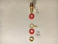
On the inside, the insulation ring goes first then the tab and as last the nut. On in other words, insolation rings go against the chassis.
Make sure that the shoulder that you can see on the top insulator sits inside the panel hole
... and, if you are rubbish at soldering like me, solder the ground tag prior to assembly. 😛
Thank you Mark and now 1 more question before I pick up the soldering iron.
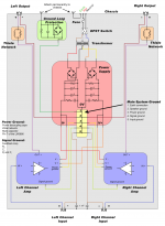
The wiring layout shows the power supply, IN_GND is connected to the tab on the RCA jack and it also goes to a 1nf capacitor which is connected to the chassis.
Does that violate the "All input connectors should be electrically isolated from the
chassis" ?
I see that there is a capacitor in between but I don't know if it helps
Good point, saves melting the insulator too. It's hard to know where to stop with the advice..........😀... and, if you are rubbish at soldering like me, solder the ground tag prior to assembly. 😛
It effectively shorts RF to the chassisI see that there is a capacitor in between but I don't know if it helps
It effectively shorts RF to the chassis
And that's a good thing huh ?
Uh-huh, it most certainly is. This will tell you pretty much all you need to knowAnd that's a good thing huh ?
http://hifisonix.com/wordpress/wp-content/uploads/2019/02/Ground-Loops.pdf
Thank you scott and i wish that i had had it before i began thri project. Its quite a work.
I will post some photos a bit later.
I will post some photos a bit later.
Photos, OK, here they come
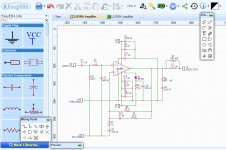
Power Supply Schematic
Amplifiers schematic
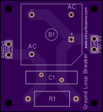
Ground Loop Protection
Wiring diagram.
Ok, here are a ton of photos. In no particular order:How about posting some photos. You didn't mention what you are building.
Power Supply Schematic
Amplifiers schematic
Ground Loop Protection
Wiring diagram.
Attachments
I read the article Scottjoplin pointed me to and at my level of expertise, (hah !), most is beyond me.
But this is what I gleaned re hum and wiring.
1) wrap the 0v, +v, and -v, around each other. I am already doing that so I am good there.
2) locate the signal connectors, for ground and signal, close together and wrap the signal wire around the ground wire.
This I did not do. The 2, signal wires are independent and the 2, signal ground wires are wrapped together.
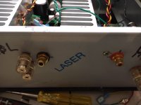
The picture shows the back of the chassis and it shows the 2 RCA connectors separated by 3.5 inches or 88mm. I put them near the corresponding amplifier and speaker connectors.
Near the top of the picture you can see the power lines red, yellow, and black, wrapped together.
So, I think that I will leave the RCA connectors where they are, and do the signal/ground wrapping solution.
What do you think ?
But this is what I gleaned re hum and wiring.
1) wrap the 0v, +v, and -v, around each other. I am already doing that so I am good there.
2) locate the signal connectors, for ground and signal, close together and wrap the signal wire around the ground wire.
This I did not do. The 2, signal wires are independent and the 2, signal ground wires are wrapped together.
The picture shows the back of the chassis and it shows the 2 RCA connectors separated by 3.5 inches or 88mm. I put them near the corresponding amplifier and speaker connectors.
Near the top of the picture you can see the power lines red, yellow, and black, wrapped together.
So, I think that I will leave the RCA connectors where they are, and do the signal/ground wrapping solution.
What do you think ?
Attachments
Regards the power wires, twisting is better than braiding, but the most important thing is that they are in close proximity so shouldn't matter too much. Yes, leave RCAs where they are, again probably ok, but twist the signal and ground together as you say. The whole idea is to keep flows and their returns (whatever they are) as close as possible and twisting also reduces interference.
Last edited:
Thank you Scott. I redid the wiring yesterday and it made a big difference. I silenced the right channel so much that it is completely silent,😀😀😀.Regards the power wires, twisting is better than braiding, but the most important thing is that they are in close proximity so shouldn't matter too much. Yes, leave RCAs where they are, again probably ok, but twist the signal and ground together as you say. The whole idea is to keep flows and their returns (whatever they are) as close as possible and twisting also reduces interference.
So what about the speakers, should I do them too ?
- Status
- Not open for further replies.
- Home
- Amplifiers
- Power Supplies
- Ground loop protection