Hi,
I'm planning to build my first tube amp with Tag Strip boards. But I have a question about ground bus bar and ground loops. If I mount some tag stripes board, and one of the tag goes to chassis with a screw and I solder the bus bar... this is a ground loop?
Thanks.
I'm planning to build my first tube amp with Tag Strip boards. But I have a question about ground bus bar and ground loops. If I mount some tag stripes board, and one of the tag goes to chassis with a screw and I solder the bus bar... this is a ground loop?
Thanks.
Attachments
you can make a ground buss and connect everything that needs grounding there, and the ground bus need not even connect to chassis, i use platic casings in some of my builds....
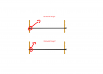
Yes, if you use that tag as a ground and do the same with another tag strip you have a loop. I always bend that tag over the strip and crimp with pliers it to ensure that I don't use it as a ground by mistake. Once you fold over that tab, the tag strip becomes stronger and you can add a dab of epoxy to the joint if you want it really secure.
The main thing to make sure is that you return the rectifier currents straight back to the transformer so they don't enter your signal ground.
As above^^^
The power supply wire as should be serialised.
That is in one side and out the other and no mixing with audio grounds.
Audio grounds should be star grounded.
The power supply wire as should be serialised.
That is in one side and out the other and no mixing with audio grounds.
Audio grounds should be star grounded.
But I have a tube book that the author uses this way.
That is commonly done, and is convenient, but is not the best way. Often they use grounded lugs
at multiple locations, which guarantees ground loops.
Last edited:
It's only a ground loop if current is flowing in the chassis where you don't want it. Get the power supply right (adequate filtering, no capacitor ripple current through the chassis, no heater current in the chassis) and you can ground anything else anywhere and be completely hum-free. Look at any 50's - 60's hi-fi construction - they knew how to do it. Star ground and bus can have hum-producing loops if not implemented correctly - keep current loops short!
1. Connect the B+ secondary center tap to the very first filter cap.
Then connect from the very first filter cap to the second filter cap.
Then connect from the second filter cap to the amplifier central ground point.
2. Do not connect the B+ secondary center tap directly to the amplifier central ground point.
A little drawing of these two, and a little thought will show you one of the best and worst
ways to wire the amp.
The first (1) keeps the high frequency transient currents in a local loop.
The second (2) puts the transient currents onto the rest of the amplifier.
That IS a very bad ground loop.
Now you know something about ground loops.
my design guidelines....
1. every power lead has its own return wire to the psu, preferably twisted pair..
2. do not rely on power supply negative return lead to run signal returns.
3. signal wires should have its own returns wire to psu ground..
4. designate a ground buss where all items that need to be at zero volts are all soldered in...this ground buss need not connect to the chassis metal work.
5. you can if you must connect the ground at a point where signal is lowest..
Last edited:
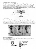
What do you think about this layout and the ground bus? Some advice?
DIY Single-Ended (SE) 6L6 / 5881 Tube Amplifier
Thanks
tube3 — ImgBB
DIY Single-Ended (SE) 6L6 / 5881 Tube Amplifier
Thanks
tube3 — ImgBB
Last edited:
Sorry missed the diagram, I would joint C11 and C13 together instead and make that your star/chassis ground, but I don't think it matters. Your RCA inputs should not ground to chassis. Just make sure you return the rectifier currents back to the transformer and prevent them getting into the signal ground. The proof is in the pudding.
Last edited:
What do you think about this layout and the ground bus? Some advice?
DIY Single-Ended (SE) 6L6 / 5881 Tube Amplifier
Thanks
tube3 — ImgBB
yes, ground bus is easy to do with this amp....i use #12 bare copper as ground bus.....
btw, triode plate resistance is low, i do not see any need for global negative feedback..i will try a 200k plate resistor going back the plate of the driver...
i have done pentode pentode single ended amps and i do not have much to complain about....
Technically would be, but I just finished a build where I did exactly this, along with another strip just below it. It's grounded to the chassis as well as jumpers across. If you're worried about hum, empirically my build has almost none. I have to stick my ear right against the woofer to hear any.
- Home
- Amplifiers
- Tubes / Valves
- Ground Bus question