Hi Sy
Yet after more searching I came across this method of managing this:
Near-zero capacitance effect for phono cables - method - Vinyl Engine
No idea if it would work, but seems easy to try
Ian.
Yet after more searching I came across this method of managing this:
Near-zero capacitance effect for phono cables - method - Vinyl Engine
No idea if it would work, but seems easy to try
Ian.
You won't get 5pF strays unless you do it on purpose;1pF is realistic. In your case you should expect about 170pF Miller from your 12AX7 .Lets swamp the cathode some and add 5pF then.
New total Miller capacitance including strays and cable = 2.3pF + (54+1)* (2.4pF+5pF) ~= 410 pF
Last edited:
Hi Merlin,
Look at Sy's post from #25.
The 5pF is for the phono cable (not strays). Its not entirely unrealistic and can easily be much worse. Its in parallel to the G-K valve capacitance so gets included in my above calculation.
At least that is what I interpreted from Sy, and it does make sense to me.
The think Sy noted is that recommended capacitive loading for many MM cartridges is lower. This often results in the cartridges sounding "brighter".
The link I provided above looks to be a creative alternative to trying to manage this in the brute-force active ways we as hobby designers might initially consider.
Kind regards
Ian
Last edited:
Not the phono cable, the wiring from the RCA jack to the grid, along with the usual inter-pin stuff. It's useful to measure it- I did with an old RCA Manual preamp-based unit.
Yes, it is in parallel with the GK capacitance - so it is NOT multiplied by the valve gain. If you get more than 180pF from a 12AX7 with a gain of ~55, you have been sloppy. Cable capacitance adds to this, of course, but is independent of the phono amp. Most people don't have more than a metre of cable, which is likely to be about 150pF at most.Its not entirely unrealistic and can easily be much worse. Its in parallel to the G-K valve capacitance so gets included in my above calculation.
Last edited:
Yes, 150pF for the cable was my estimate as well, and the two cables I have here both fall in that range. So in order to accommodate many MMs, the input C has to be pretty low because even a good cable eats much of the capacitance budget.
The other aspect is tube to tube variation- if the input C is low, the cable dominates and that's a lot more stable and repeatable.
Sorry, I didn't catch that he was trying to add that into the Miller portion.
The other aspect is tube to tube variation- if the input C is low, the cable dominates and that's a lot more stable and repeatable.
Sorry, I didn't catch that he was trying to add that into the Miller portion.
Hi Merlin
You are 100% correct! Many thanks for your sharp eyes! I went back over the formula and if the cable were in parallel with G-A then it would be added to the A+1 muliplier, but it is of course in parallel with G-K so is simply additive. phew!
So this evening I pulled apart my phono box and did some measurements. Indeed, strays are a bit higher than my estimated 0.7pF but not by much. Your estimate of 1pF is really decent.
I use ceramic sockets. I have them mounted completely independently - not on a circuit board. My work is never sloppy. I think this is perhaps an important tip for others.
Now, I measured my phono cable (Litz really) which oes all the way from the phono amplifier to the pick-up, straight through. It has quite some capacitance at 33pF but this decent enough. I know there are exotic enough cables out there that get even lower.
So, Let's re-do this calculation from scratch:
Cgk = 1.6pF + 1.0pF stray = 2.6pF
Cgp = 1.7pF + 1.0pF stray = 2.7pF
Ccable = 33pF
A=54 (non-bypassed, which is my choice - it is fully accounted for in my RIAA)
Cin =Ccable + Cgk + Cgp*(A + 1)
Cin = 33pF + 2.6pF + (54+1)* 2.7pF = 151.1pF
Cin = 184.1pF
Now.. this number is indeed looking more in line. Thanks again for your sharp eyes. Sy is correct - the cable does dominate. If you are getting 150pF on the cable, then it is not suitable for phono..... this is one area where the user could easily make improvement. There are many suggestions online.
The strange thing is now is that I am tempted to ADD small capacitance for my Nagaoka MP-11 cartridge. hmmm... nah. I will leave it just as it is.
This was a very good exercise. I still don't know how we got away from the original topic though.
I still like 12ax7 for MM phono. Its exceptionally linear. The high Rp that will likely drift over time is the only concern, but so far I am quite happy.
Ian
Not the phono cable, the wiring from the RCA jack to the grid, along with the usual inter-pin stuff. It's useful to measure it- I did with an old RCA Manual preamp-based unit.
Hi Sy
Did it use a circuit board? were the sockets ceramic? Just curious as my measurements were significantly lower. I suspect circuit board + bakelite adds much.
Ian
Also - the RCA connectors can add quite some capacitance on the amplifiers of old...
Quality connectors ones use PTFE and have very low capacitance. XLR might also be worth considering too.
Ian
Quality connectors ones use PTFE and have very low capacitance. XLR might also be worth considering too.
Ian
Point to point. Best measurement method (IMO) is series resistance at input and measure f3 (requires disconnecting following stages and high impedance probe at output of first stage).
It is hard to find one lower without other compromises.
If you are getting 150pF on the cable, then it is not suitable for phono.
It is hard to find one lower without other compromises.
It is hard to find one lower without other compromises.
I used some surplus PTFE insulated copper litz lacking all the marketing characteristics that audiophools spend foolish money for. Its probably 30 AWG. Including insulation it measures 0.45 mm in diameter. It was quite frankly... cheap.
During testing, I discovered that I could get away without shielding it. The most expensive part of my tonarm wiring are the bullet plugs.
I use a tonearm which does not have a tube based wand. 😉
Ian
I only had time this past weekend to wire up a Slagleformer AVC volume control (yay!), and run the TubeCAD RCA-with-Aikido-CF circuit through LTspice.
I took the same two stages of 12AX7 and simulated them, one with a plain R-loaded CF and the other with the Aikido-style CF. Is it possible that a regular old R-loaded cathode follower will yield lower distortion than the Aikido-style CF?
Question for anyone who's used LTspice a lot:
I know you can't trust LTspice to predict THD accurately in terms of 'this circuit will give you xxx% THD at 1V RMS output', but what about relative THD levels? For instance, if I increase the B+ to a circuit from +325V to +375V, I might notice a useful drop in THD at the same output level. That agrees with what one would expect in reality. Do you think LTspice can predict that improvement with any kind of accuracy?
--
Hi rongon
Why would you consider using a 12ax7 as a cathode follower? I would use a different valve/tube. You have a lot of options.
Ian
Why would you consider using a 12ax7 as a cathode follower? I would use a different valve/tube. You have a lot of options.
Ian
Oh, sorry. The first two gain stages would be 12AX7, the CF would be something like a 12AT7 or 12AU7. I guess I could use a 6SN7. But the CF would not bea 12AX7.
--
--
Member
Joined 2009
Paid Member
I guess you could make a workable RIAA preamp with a 12AX7 in first stage and 12AU7 in second stage. Gain would be in the 40dB area (I think).
12AU7 max gain is only about 15 to 18X in real life. The gain would be too low using nothing but 12AU7's. Same with 6SN7 or 6FQ7. Not enough gain.
Using two 6DJ8 (ECC88) triodes would work, but I think the gain would be in the 34 to 36dB range. That's OK for use with a line preamp with gain, but that won't work in my case.
I was thinking of something like 12AX7 common cathode > 12AX7 common cathode > 12AU7 cathode follower. Or maybe the cathode follower could be a 12AT7, or even a 12AV7 (because I have a bunch of those).
--
Last edited:
Hi Bigun
Depends how you do the RIAA correction.
If you want to do it in a single shot, you will probably need to attenuate as much as 40dB of the higher frequncies. This would suggest that you will need to amplify the signal quite a bit (100x or 40dB) before correction. Of course, it can be less, but the signal going into the 2nd stage will be even weaker than the input.
This would clearly preclude 12au7 for single stage RIAA at input.
However, Don't forget the possibility of correcting for RIAA over more than one stage too. This might be a way to successfully use 12au7. The less-linear frequency response might be an advantage to exploit.
There are many possibilities.
One unusual way would be 12ax7 input to linearly boost the uncorrected signal, then use 12au7 in a singal RIAA correction step. After this, you might get away with a 6DJ8 amplification + follower combination. No idea if this has ever been attempted 😉
Or split the RIAA correction over multiple stages. I think you get the idea.
Ian
Last edited:
Ah, yes, very true. If you use a passive 'split RIAA' using three stages, then yes, you could use something like a 12AU7 for the first and second stages. However, you would then need three stages of lower gain, instead of two stages of higher gain.
What would be the issues introduced by using three gain stages? Besides needing more parts, of course.
More tubes would mean more tube self-noise.
Cascaded stages will result in a different distortion profile, correct? Probably more odd-order harmonics in the distortion products.
To get to about 48 to 50dB gain with RIAA correction, I remember simulating a setup with 6DJ8--2k122Hz LPF > 6SN7--50-500Hz shelf > 12B4A output stage.
If I remember correctly, the all-in-one-go EQ with 12AX7 > 12AX7 > 12AU7 cathode follower looks great in simulation. But in the real world?
My goal here is to use a few of the 12AX7's and 12AT7's I have left over from my guitar playing days in a relatively inexpensive, low-current phono preamp.
--
PS - I have a friend who's telling me I should use 6SL7 instead of 12AX7, because they 'sound better.' That might be fun for use with a HOMC like Denon DL110, where input capacitance is not an issue. Fortunately for me, that's exactly the cartridge I'm using.
--
Last edited:
Member
Joined 2009
Paid Member
I would assume that multiple stages is OK when designed properly. I have some 3A5 tubes I bought (can't help buying tubes) and some chap made an RIAA out of these before even though they have a mu of 15. Actually, I only got a turntable recently and have but two records so this RIAA stuff is new to me - I'm currently laying out a PCB for a transistor version (TGM1i thread) but I like to follow information on tube RIAA. I would like to clone the Shindo Claret as first attempt, I'm not sure I'm brave enough to design from scratch and I have all the design details for the Shindo as well as one of his power amps so I thought I'd make an all-tube integrated.
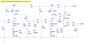
Here's what I'm thinking (attached schematic). 360V B+ supply, 1mA plate current and 220k plate load resistors for each 12AX7, DC coupled to a plain old 12AT7 cathode follower with 3.5mA plate current. I can plug a 12AU7 or a 12AV7 into the cathode follower spot and the performance hardly changes.
I was thinking of trying a Morgan Jones Statistical Regulator-style power supply. It would take twenty-four 15V zener diodes to make the zener string. I have a 30uF motor run cap I could use as the final bypass cap.
I also ran a simulation of the same circuit with 100k plate resistors on the 12AX7's, from a 300V B+ supply. The prediction is for about twice the distortion and about 15% lower gain. That should still work well, though. Distortion is predicted to be low for either version.
--
Attachments
- Status
- Not open for further replies.
- Home
- Amplifiers
- Tubes / Valves
- Grid-cathode voltage and grid current in 12AX7?