true, but for such tiny signal, the miller capacitance doesn't seem to be so influential.. even for the relatively inexpensive MM's I like to use these days... 🙂
MM frequency response is extremely sensitive to load impedance. Here's an example of the changes in frequency response for a very good MM (Audio Technica 150MLX) into the load capacitance typical of a 12AX7-based preamp plus the inevitable cable capacitance.
Attachments
MM frequency response is extremely sensitive to load impedance. Here's an example of the changes in frequency response for a very good MM (Audio Technica 150MLX) into the load capacitance typical of a 12AX7-based preamp plus the inevitable cable capacitance.
How do you arrive at the 500 pF capacitance? How much of it is caused by the miller capacitance of the 12AX7 and how much by the cable?
+1
I think I have a working understanding of this...
Since MM cartridges have a tiny magnet moving around inside a coil, that coil has to have quite a few turns of wire, and so will have appreciable inductance. That series inductance, combined with the 47k load resistor, forms an LCR filter when combined with the parallel capacitance presented by the input tube Miller effect and whatever strays and cable capacitances there are. So that's an LCR filter with a series L (and series R of the cartridges coil), parallel C, and parallel R.
With a 12AX7, the triode's Miller capacitance can be 200pF or more, all by itself. Add maybe 250pF of cable capacitance, combine that with the 47k load resistance, and you have enough that it can present a problem.
However, you don't have to leave the load R at 47k. If you reduce that value, you change the shape of the LCR filter. There are a few people who've experimented with some Shure MM carts, and found that if you use about 340pF parallel C (perhaps supplied by the 12AX7) and reduce the load R to 38k, they like the sound of the result.
So one can play around if one wants to.
However, it remains true that MM carts are touchy about the load C. It can make a good one sound wretched. It might be why I have friends with tube preamps who never liked Grado carts.
--
PS - Since I'll be using high output moving coil cartridges, I'm not sure a 12AX7 would be so terrible.
--
Last edited:
How do you arrive at the 500 pF capacitance? How much of it is caused by the miller capacitance of the 12AX7 and how much by the cable?
I broke the numbers down in detail in the Equal Opportunity article in Linear Audio, and confirmed by measurement. Jan will forgive me for plagiarizing a paragraph excerpt:
A “classic” tube phono stage (e.g., Marantz, Dynaco, Audio Research) will use a 12AX7 in the first stage. The gain using their parts values is roughly 70. 12AX7 grid-to-plate capacitance is specified at 1.7pF, and usually runs a bit higher than that; several tested samples of 12AX7/ECC83 for various manufacturers had figures closer to 2.5pF. Wiring and strays add another 4-5pF to that. It’s then readily determined that the input capacitance from the Miller effect (which swamps the grid-to-cathode capacitance) is close to 500pF! Even if we select tubes for low capacitance and wire carefully, the best we could hope for is perhaps 350pF. FET circuits will show similar results, with a larger contribution from the gate-to-source capacitance. Let’s take the Panglossian figure of 350pF, add the cable capacitance and go with that, for a total load of 500pF on the cartridge.
I broke the numbers down in detail in the Equal Opportunity article in Linear Audio, and confirmed by measurement. Jan will forgive me for plagiarizing a paragraph excerpt:
"Wiring and strays add another 4-5pF to that"
But I suppose this part will be the same if one uses another valve (though it is not amplified as much as with the 12ax7). Careful wiring is important it seems. Thanks for the explanation.
But I suppose this part will be the same if one uses another valve (though it is not amplified as much as with the 12ax7). Careful wiring is important it seems.
Yes, exactly, you get the same issues with other high mu tubes in grounded cathode. One major contributor is the wiring from input jack to the grid, and it's not easy to minimizes that.
Shure MM's are known for preferring a high C load.
With the exception of a few freaks (e.g., the Technics EPC100CMk4), every MM will have an optimal capacitance to achieve flattest response. Shure was kind and comprehensive enough to publish data on the effects of different capacitance loads on its V15 cartridges, but most good manufacturers will at least give a recommended optimum that should be close.
To get rid of Miller, turn down the gain 😀
With a cascode the gain is round 1x for the lower one.Better put an extra C to keep HF rubbish out.
An other advantage is the high output impedance, determined now almost completely by the load.
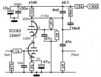
Like this ? 😉
Mona
With a cascode the gain is round 1x for the lower one.Better put an extra C to keep HF rubbish out.
An other advantage is the high output impedance, determined now almost completely by the load.
Like this ? 😉
Mona
Attachments
MM frequency response is extremely sensitive to load impedance. Here's an example of the changes in frequency response for a very good MM (Audio Technica 150MLX) into the load capacitance typical of a 12AX7-based preamp plus the inevitable cable capacitance.
Hi Sy
Did you actually measure this or is your plot a simulation? I have done relatively simple point measurements and don't see 3dB loss at 15kHz with my Nagaoka.
I used the inherent high frequency roll-off characteristic when tuning my RIAA. Old-school designers did this all the time. But you do need to keep the plate below 120V, despite a high B+ of 300V or more. The loads can be pretty exotic looking...
It also is a huge help to use a good inverse RIAA network to tune the circuit for 12ax7. Don't get me wrong - I have also done MM phono with triode strapped pentodes similar to your amp. But to roundly dismiss 12ax7 for phono duty when it can do a pretty darn good job is not so fair.. With all due respect - just my opinion 😉
Ian
Last edited:
To get rid of Miller, turn down the gain 😀
With a cascode the gain is round 1x for the lower one.Better put an extra C to keep HF rubbish out.
An other advantage is the high output impedance, determined now almost completely by the load.
Like this ? 😉
Mona
This is another valid solution. I remember some Grant phono amps that used this kind of method.
Ian
How do you arrive at the 500 pF capacitance? How much of it is caused by the miller capacitance of the 12AX7 and how much by the cable?
Miller capacitance is fairly straightforward to calculate.
Cgk = 1.6pF + 0.7pF stray = 2.3pF
Cgp = 1.7pF + 0.7pF stray = 2.4pF
If we do unbypassed cathode, with a plate load of a 370K and bias to around 1V at 0.5mA then you are looking at a amplification factor of around 55.
Av(unbypassed Rk) = (mu*Rp)/(Rp+ra')
But the unbypassed cathode increases ra' - example: ra'(unbypassed Rk) = ra + (mu + 1)*Rk - in this example, with only 0.5mA current, ra is about 80k Ohm according to the GE specs sheet.
So for this example ra' = 80k + (100+1)*2.2k = 302.2K and the amplification factor becomes = (100*370k)/(370k+302.2k) = 55
Therefore Miller capacitance of the 12ax7 stage alone will be 2.3pF + (55+1)* 2.4pF = 136.7pF
Now.. how will this effect 3dB upper frequency roll off? Let's remember that we have a 47k Ohm load resistance for MM.
f = 1/(2*pi*R*C) = 1/(2*pi*47k*136.7pF) = 24.8 kHz
Sounds pretty decent, but as Stuart mentions, there are things that add to the miller capacitance... MM cartridge itself and the cables for example.
In Stuart's example, he claimes a total input capacitace (cartridge plus cables plus miller capacitance) of a whopping 500pF (!) This would theoretically experience 3dB high frequency roll off at around 6.8 kHz
This sounds pretty dire. BTW - You can do the same for a Triode strapped D3a. If you use a CCS then it can be useful to simply estimate the plate load to 1M. If you bias using an LED then do the calculations for a by-passed cathode instead to determine ra' I did those calculations and the miller capacitance was actually worse than 12ax7 (assuming MM input). Maybe I should do them again just to be sure...
So, what does this mean? Does Stuart suggest MM should be generally hung? I can't comment for him on this and expect he might have more to add. 🙂
However... look at it this way: The whole point of a phono stage is amplify the signal enough to neatly and progressively roll off the higher frequencies to match the RIAA curve. After RIAA equalization the signal invariably must be boosted again to get to line-level, and then usually requires some output buffer to drive a reasonable load such as a cable. ok?
So perhaps the inherent high frequency roll-off can be used to our advantage (if we are careful).
Beyond using an inverse RIAA network, it is therefore probably wise have to use a test record with frequency values to do MM well. Mine is admittedly not so great - it just has discreet signal levels - the highest being 15kHz - which I simply can't hear at all anyway. There are far nicer once out there.
Btw - this also means that using an MM phono stage for MC (or the opposite) not such a brilliant idea...
Ian
Last edited:
Did you actually measure this or is your plot a simulation?
This particular plot is a sim, based on the actual electrical characteristics (L, R) of that cartridge (the 150MLX). There's plenty of published experimental data for other MMs showing this effect.
That doesn't hang MMs, but it does demonstrate that the manufacturer's recommended loading should be taken seriously, and in that specific case, why inattention to this (or poor preamp design) has given that particular cartridge a reputation for brightness. Load it right and it sounds great, as I demonstrate to myself daily.
Your calculation is not correct. The load is in shunt with the cartridge's L and R, not series. And you have to normalize against recommended load because of the cartridge's mechanical response.
This particular plot is a sim, based on the actual electrical characteristics (L, R) of that cartridge (the 150MLX). There's plenty of published experimental data for other MMs showing this effect.
That doesn't hang MMs, but it does demonstrate that the manufacturer's recommended loading should be taken seriously, and in that specific case, why inattention to this (or poor preamp design) has given that particular cartridge a reputation for brightness. Load it right and it sounds great, as I demonstrate to myself daily.
Your calculation is not correct. The load is in shunt, not series. And you have to normalize against recommended load because of the cartridge's mechanical response.
I actually though of that while writing it, but thought it would be an interesting way to elicit a response 😉
Could you be so kind as to explain your 500pF value?
Btw - my gain is only 54.. since input impedance of next stage is 1M. Sorry I left that part out.. 😉
Lets swamp the cathode some and add 5pF then.
New total Miller capacitance including strays and cable = 2.3pF + (54+1)* (2.4pF+5pF) ~= 410 pF
Looks big! Its a good thing I account for it in my RIAA anyway.
Also - while Da3 is worse for input capacitance, it is in a way better to work with than 12ax7 for other reasons. It has such a low plate resistance, which means it is easier to use standard values. Changes in plate resistance over time won't significantly effect RIAA correction... But 12ax7 plate resistance changes will be significant over time and the RIAA correction will become incorrect.
Frequency sweep records are not expensive btw. Then you don't need to make simulations which might or might not be subject to other errors.
Ian
Last edited:
Hi Sy
I was just looking up recommendations on my nagaoka online and found a user on another forum who suggested my old Nagaoka MP-11 worked well with 450 pF input capacitance and even higher...
http://www.tnt-audio.com/sorgenti/nagaoka_mp11_e.html
Guess I'm just lucky. Some of my previous MM carts were Shure, and many users found it useful to ADD capacitance to them.
So for the MM carts that don't manage tube-level input capacitance well, the only alternative would seem to be solid state. Correct? I suppose someone has compiled a list somewhere.
I'm still searching for L and R values for my MP-11..
Ian
Last edited:
So for the MM carts that don't manage tube-level input capacitance well, the only alternative would seem to be solid state. Correct?
Nope. 😀 There's other ways to handle the issue- lower mu, cascoding, grounded grid, buffering...
Ok, I've done some of these things for MC before, but never really considered it for MM.
Chiefly due to manufacturer recommendations.... but now it makes much more sense. I suppose I have been lucky with my relatively limited choices in MM cartridges until now.
I'm glad you managed to get your 150MLX down to 100pF-200pF range that is recommended. If it were me I would try a buffer stage. sounds like a nice challenge!
Ian
- Status
- Not open for further replies.
- Home
- Amplifiers
- Tubes / Valves
- Grid-cathode voltage and grid current in 12AX7?