wow yes that pd driver is far better, I didn't know CPC had such a larger range than onecall I thought all stock was the same. As for skytronic drivers I think the problem is incorrect data entry as I think the cms should be 93.4um/N not 934 then the parameters don't contridict. I have some 10" skytronics and they behave as simulated. Anyway I will look more into easy to build tapped horns, thanks for the help.
Take a look at some finished projects to get the idea.
I would look at a cutoff near 40hz.I cant believe how cheap that 12" PD is ! Here for that all you get is a high Q car sub !
http://www.diyaudio.com/forums/subw...ted-tapped-horns-collaborative-th-thread.html
Ok I have a number of questions about the pd 12":
Precision Devices International Limited
1. What is the maximum safe compresion ratio? the cone is paper but looks good quality so I would estimate 3:1 if cheap 8" drivers can take 4:1, but I have no experiance
2. What is the LE of the PD driver, two inductance mesurments are given presumably two voice coils? if so my driver would be the 8ohm version.
3. A loaded and unloaded RMS are given, which is more suitible for Hornresp?
4. I'm looking at the tutorial here which describes a horn with an outlet on its longest dimension, I want to make a horn that is tall verticaly and so need to close the bottom like:
Is there a way of modeling this in Hornresp? or do we just assume that the corner dosn't exist?
Do you want a tall enclosure or a folded one?Ok I have a number of questions about the pd 12":
Precision Devices International Limited
1. What is the maximum safe compresion ratio? the cone is paper but looks good quality so I would estimate 3:1 if cheap 8" drivers can take 4:1, but I have no experiance
2. What is the LE of the PD driver, two inductance mesurments are given presumably two voice coils? if so my driver would be the 8ohm version.
3. A loaded and unloaded RMS are given, which is more suitible for Hornresp?
4. I'm looking at the tutorial here which describes a horn with an outlet on its longest dimension, I want to make a horn that is tall verticaly and so need to close the bottom like:
Is there a way of modeling this in Hornresp? or do we just assume that the corner dosn't exist?
The bass doesnt see the corner since it is small relative to the 8metre wavelength.If however we were talking about 900hz that would be another matter.
No idea about loaded/unloaded RMS just enter the lower number
3:1 appears a good rule of thumb
Dont worry too much about le its mainly the low pass filtering element,just guestimate ,or see what a few similar sized woofers are eg compare eminence or 18sound 12"
Did you check out the pictures thread
THs seem to get built mostly like this and they seem to measure according to their Hornresp simulation without this "corner".
At these low frequencies it won't matter much I guess.
At these low frequencies it won't matter much I guess.
Last edited:
thanks! design seems to be going ok so far, basicly current constraint is that it should fit somehow in a prius with 4 people in aswell due to finding a time slot to build it in the summer when I am home and needing to take it back to London. The reasons for this mainly revolve around the nearest source of MDF to me at the moment been 5miles away and only having public transport to get there wheras at home I can drive to an actual wood yard and get peices cut to size.
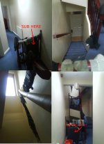
I have enclosed a picture showing where the sub is located, this is wall loading so in hornresp I need 1pi space loading?
so tall is good then I can make the main speakers tall and just place next to it, my original dimensions were based on putting the mains ontop of the sub. However height is ultimatly constrained by having to transport it in a car with a maximum of 1 seat down, I could however potentialy construct intialy with screws and flat pack so would prefer the longest dimension to be slightly less than the diagonal width of a prius boot. May not be posible wherupon creativity may be needed.
Mesuring the room using my current subs playing pink noise without their EQ curve and comparing with there outdoor no EQ mesurment shows nodes @ 20Hz and 40Hz, managed to lose my memory stick with the plots though 🙁
Attachments
I just saw your post and have come up with a very simlar design so far, my RMS value is very different though, where did you find yours?
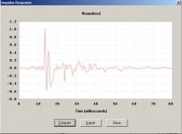
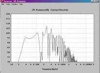
also my SPL plot is much more extended but my impulse response is awfull is this because my horns mouth is too small?
if so will having this bad impulse response be a real problem considering the non hi-fi usage?
Attachments
PRECISION DEVICES PD.12SB30 - U.K. International Cyberstore
Supposedly ships to US as well.
Can any one tell me why the pic in the PDF is different from the site and which is right?
Pic on the site looks lite the PD.122(PDF)
"2. What is the LE of the PD driver, two inductance mesurments are given presumably two voice coils? if so my driver would be the 8ohm version."
It's a single VC. L1 (0.999mH) is the right one. Some simulation software can take advantage of L2 and Res.
According to UniBox it better models impedance at HF due to eddy currents in the pole piece.
I did the original design in AkAbak, which is still on my computer.
| 40 Hz Tapped Horn
Def_Const |Horn Dimensions
{
a1 = 150e-4; |Area at throat (cm^2)
a2 = 250e-4; |Area at rear of driver (cm^2)
a3 = 1300e-4; |Area at front of driver (cm^2)
a4 = 1400e-4; |Area at mouth (cm^2)
l1 = 10e-2; |Distance from throat to rear of driver (cm)
l2 = 240e-2; |Line distance from rear of driver to front of driver (cm)
l3 = 25e-2; |Distance from front of driver to mouth (cm)
}
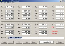
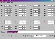
Def_Driver 'Dr1'
| PD.12SB30
Sd=530.9cm2
fs=50.238Hz
Qes=0.316
Qms=5.024
Vas=58.945L
Re=5.493ohm
Le=1.773mH
system 'S1'
Driver Def='Dr1' Node=1=0=3=4
Waveguide 'W1' Node=2=3 STh={a1} SMo={a2} Len={l1} Conical
Waveguide 'W2' Node=3=4 STh={a2} SMo={a3} Len={l2} Conical
Horn 'H1' Node=4 STh={a3} SMo={a4} Len={l3} Conical
Note that it is in 2Pi, the Hornresp design is in 1Pi (making it louder).
I also have AkAbak files on drivers from JBL, Ciare, RCF, but the PD looks like the most bang-for-the-buck.
30hz is all fine and good, but dance music only very rarely gos below 40hz, so it is a waste (unless you have unlimited time, money, transport, etc. Also, the 240cm length is possible from 120cm sheet without the problems of your 300cm length.
"my impulse response is awfull"
Impulse response determines the HF response, who cares? You are not going to run it past 100hz, are you?
"Supposedly ships to US as well."
Not economical.
| 40 Hz Tapped Horn
Def_Const |Horn Dimensions
{
a1 = 150e-4; |Area at throat (cm^2)
a2 = 250e-4; |Area at rear of driver (cm^2)
a3 = 1300e-4; |Area at front of driver (cm^2)
a4 = 1400e-4; |Area at mouth (cm^2)
l1 = 10e-2; |Distance from throat to rear of driver (cm)
l2 = 240e-2; |Line distance from rear of driver to front of driver (cm)
l3 = 25e-2; |Distance from front of driver to mouth (cm)
}
Def_Driver 'Dr1'
| PD.12SB30
Sd=530.9cm2
fs=50.238Hz
Qes=0.316
Qms=5.024
Vas=58.945L
Re=5.493ohm
Le=1.773mH
system 'S1'
Driver Def='Dr1' Node=1=0=3=4
Waveguide 'W1' Node=2=3 STh={a1} SMo={a2} Len={l1} Conical
Waveguide 'W2' Node=3=4 STh={a2} SMo={a3} Len={l2} Conical
Horn 'H1' Node=4 STh={a3} SMo={a4} Len={l3} Conical
Note that it is in 2Pi, the Hornresp design is in 1Pi (making it louder).
I also have AkAbak files on drivers from JBL, Ciare, RCF, but the PD looks like the most bang-for-the-buck.
30hz is all fine and good, but dance music only very rarely gos below 40hz, so it is a waste (unless you have unlimited time, money, transport, etc. Also, the 240cm length is possible from 120cm sheet without the problems of your 300cm length.
"my impulse response is awfull"
Impulse response determines the HF response, who cares? You are not going to run it past 100hz, are you?
"Supposedly ships to US as well."
Not economical.
My freind has just pointed out two timber merchants within walking distance who stock 3m 18mm MDF so height is now only limited by ceiling! 😀 so definatly aiming for f(-3dB) = 33Hz now.
OK, then just running the numbers' for an oversize DTS concept to ~handle up to the driver's Pe rating while staying within your ~480 L bulk limit:
GM
GM
Attachments
..😀 so definatly aiming for f(-3dB) = 33Hz now..
Good driver,why not aim at a lower f-3dB?🙂
b
Attachments
Yeah, this driver has such a high mass corner that it 'wants' a tuning well below Fs, especially if 'blown up' to fill a specific bulk to keep it from being technically under-damped as my sim. WRT its HF mass corner, I just now noticed that the sim I did won't work as is since its L12 value must be 16 cm minimum to mount the driver, so its response should be a bit different than predicted beyond the known variances. Of course without measured specs of the actual driver used, this is all just pure conjecture.............
GM
GM
Well driver is ordered now, could have got it from onecall for an amazing 60GBP but out of stock till late August 🙁 So went for BlueAran instead.
My previous simulation I acidently had a throat chamber but it didn't effect the response, slightly confused over this.
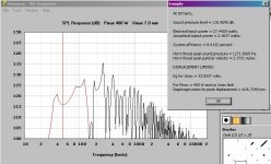
looking at bjorno's simulation I like the idea of 108dB @ 20hz but I am unsure of the physical reprensation of the S5 section. Is this the new horn mouth and if so why not just extend the L34 section instead of adding a new section?
My previous simulation I acidently had a throat chamber but it didn't effect the response, slightly confused over this.
looking at bjorno's simulation I like the idea of 108dB @ 20hz but I am unsure of the physical reprensation of the S5 section. Is this the new horn mouth and if so why not just extend the L34 section instead of adding a new section?
This one is interesting and a lot of really good responses .
My treatment would be first find a cheap /used single 18" IE EBAY .
One with the lowest VAS possible . Most PRO 18's are around 98 dBM efficiency
So a little power will drive it a long way .
You can always find singles on ebay , but pay attention to the VAS , lower value is better for this application. ie EV DL18 is 100 dB 400 wat driver using a 2.65" coil .
When puzzle-coated these thing work amazing well.
Next tune the cabinet higher than normal ie around 80 Hz , the Roll off at that efficiency will still give you plenty of usable 30 HZ and will limit the box size down to something usable. , next in your box program try to underdamp the response curve slightly it will produce a nice 3 dB gain hump at the 80 .
Thats my 2 cents . I've built bass players rigs that way and most of then are blown away with how much better an 18 is at producing usable bass .
thats how my current bedroom sub stack works, getting 30Hz out of an 80Hz tuned box though requires alot of gain (>12dB) that totaly kills the maximum spl, also results in alot of cone excursion and loss of efficinacy. Works well for small low SPL subs but I am doubtfull about higher SPL aplications.
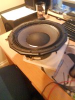
My sub has arrived, very well made bit of kit, completly solid construction about 1/2" thick basket and push fit terminals.
Still unsure of S5 in relation to the tapped horn if anyone has any insight.
Also how would I go about modeling positioning the driver low on the central board such that S3 is efectivly 0?
Attachments
Reply ;thats how my current bedroom sub stack works
Yeah I uderstand what your saying , but most car audio subs start at typ around 86-88dbm efficiency . You have to have 40 watts to just get up to meet what the 18" starts out at.
The original indication was that you did'nt have much power.
ie 80 + 80 watts
ALthough 80Hz seams high as a tuning frequency the roll off stays relatively flat down to resonance in the smaller tuning and almost all people don't actually hear 30 hz , you feel it but not hear it.
The kick part of bass response is always around 60 - 80 and while its possible to hear 35 or 40hz , 30 becomes rumble more than anything.
Where I live we are at 3500 ft above sea level , sound travels slowly and
requires much bigger cone area to get bass response . Ie a 15 at sea level
does what an 18 does at my altitude.
I hope your system works out well whatever you end up with.
Regards...Rck
Still unsure of S5 in relation to the tapped horn if anyone has any insight.
Also how would I go about modeling positioning the driver low on the central board such that S3 is efectivly 0?
HR allows either a three or four segment TL/TH to be designed and according to the HELP files, for a four segment the driver is at S4 and the mouth at S5 whereas for a three segment the driver is at S3, mouth S4, ergo S3 is just a phantom point between S2, S4 in bjorno's design as shown by it being just dashed in.
GM
Long time no update...
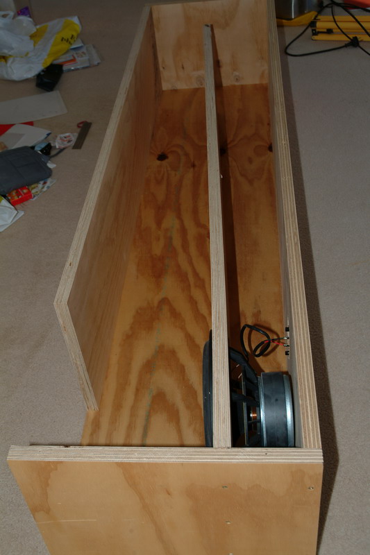
I ended up going with a tapped 'pipe' with no expansion as the sims indicated only a slight increase in pass band ripple for this configuration.
Initially I had the mouth of the pipe forming a 90 degree bend at the driver end however this didn't work well with lots of turbulent air between the magnet of the driver and the upper edge of the mouth. I think this was because the driver was located too close to the mouth and has a large magnet.
Anyway I had very little time to work on this project so I created an expanded mouth shown in the pics just to get things working. This worked well for a year at my old house and having recently moved house I had time for some pictures and measurements.
At one point I totally fused the voice coil playing sine wave test tones as I was sat in a null and didn't realise just how loud I was going. So the woofer has been through a recone. As a point of interest the PD.12SB30 did take 1.2KW for about 30S before failure.
Anyway measurements coming in the next post.
Attachments
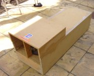
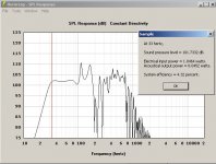
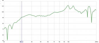
Heres the data. 2.84V SPL taken at a lower level and adjusted to avoid equipment overload. Used ECM8000 mic with generic .cal file and radio shack SPL meter again with generic cal. Just in back yard as shown in earlier pic.
Attachments
- Status
- Not open for further replies.
- Home
- Loudspeakers
- Subwoofers
- Greatest output for space