You can not recondition coupling caps, only electrolytics. Modern Polyprop caps are so much better than old mainly paper caps and they are so cheap. Even modern paper caps are unreliable and expensive.
Phil
Phil
I think you have settled on the right philosophy - to test and recondition where possible/sensible. But if you find multiple instances of certain types/values being leaky, its prudent to replace the other similar ones too.turns out all the coupling caps are leaky. One is passing practically all the input dc. I shall attempt to recondition the rest as I would like to keep the original caps if at all possible.
hi yes I have several nice Jensen replacements but it seems to be a bit of a sacrilege to change out the originals, but i'm kinda stuck if I can't reform them. I was under the impression that it was possible to reform the older metal can PIO caps, but i'm pretty new to this and really not that well informed
Attachments
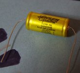
There are excellent axial film capacitors available.
Whit a little handywork you can re-use the old shell and put a modern film capacitor in.
Whit a little handywork you can re-use the old shell and put a modern film capacitor in.
i Have just put dc across the new cap and it drops off to practically 0 but with the old caps there's 200v and little drop. I could restuff the cans and put in a film cap. It seems like the best solution as I don't think I can reform the old ones.
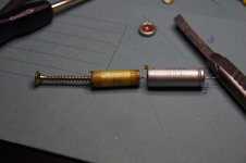
I restiffed the 8uf and it came out well
I restiffed the 8uf and it came out well
My first hifi experience was a pair of mcintosh mc30s that had sat in my Inlaws attic for a very long time. I started them slowly with a variac...over a few hours and all the electrolytic caps came to life just fine. The old film caps were almost all bad. I was able to replace them with modern parts that I hid in the hollowed out cases of the old parts. I new nothing of how the things worked but i had a multimeter could find bad parts and solder in new ones. When I learned the value of the amps I instantly sold them for what at the time was two months of payment on our home. Have fun...be careful.
Evan
Evan
With those old capacitors they can be restored as long as the electrolyte has not leaked
Don't even bother trying to reform them. They WILL fail either sooner or later. Capacitors have a finite lifespan. Spend the extra few bucks and buy new ones. I would never trust 50+ year old capacitors to protect thousands of dollars in tubes.
Last edited:
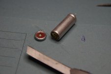
hi thanks for all the advice. I managed to get some vishay caps which will fit inside the case of the TCC metalcaps
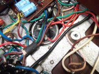
I have started to dissemble them and I must say it is coming along nicely. Some rubber sleeving for insulation. The new caps leads will go through the existing holes and the end can be epoxied on. I can touch up with silver paint pen for that original look.
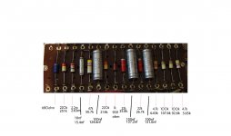
A lot of the resistors are out of spec so that will not be such an easy thing to hide. Might just need to fit new.
I have started to dissemble them and I must say it is coming along nicely. Some rubber sleeving for insulation. The new caps leads will go through the existing holes and the end can be epoxied on. I can touch up with silver paint pen for that original look.
A lot of the resistors are out of spec so that will not be such an easy thing to hide. Might just need to fit new.
Attachments

Paper in oil capacitors cannot be reformed, electrolytics in some instances can be if the dielectric has not dried out. In general it is not a bad idea to replace all paper coupling capacitors and the electrolytics whether or not they can be reformed.
Don't even bother trying to reform them. They WILL fail either sooner or later. Capacitors have a finite lifespan. Spend the extra few bucks and buy new ones. I would never trust 50+ year old capacitors to protect thousands of dollars in tubes.
My experience is that once they are old they either carry on working or begin to leak electrolyte and go open circuit putting lots of hum on the audio. Mine took three days and only one of four identical mono blocks lasted only 6 months before the two double 32uf cans went open circuit.
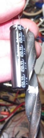
LCD panel mains capacitors (long and skinny type) can be fitted without removing the can from the chassis with the correct size of drill and a spot of epoxy.
The capacitors are cheap and can be got on both sides of the Atlantic.
450BXW33MEFC10X40 - RUBYCON - CAP, ALU ELEC, 33UF, 450V, RAD | Newark element14
450BXW33MEFC10X40 - RUBYCON - CAP, ALU ELEC, 33UF, 450V, RAD | Farnell element14
Drill small pilot holes and work up to the full drill size and use another full size drill to stop the internal material from rotating inside the can especially if you have drilled through the solder tag.
The fixing screws are hard to get to on my vintage mono blocks.
Attachments

Paper in oil capacitors cannot be reformed, electrolytics in some instances can be if the dielectric has not dried out. In general it is not a bad idea to replace all paper coupling capacitors and the electrolytics whether or not they can be reformed.
My experience is that once they are old they either carry on working or begin to leak electrolyte and go open circuit putting lots of hum on the audio. Mine took three days and only one of four identical mono blocks lasted only 6 months before the two double 32uf cans went open circuit.
LCD panel mains capacitors (long and skinny type) can be fitted without removing the can from the chassis with the correct size of drill and a spot of epoxy.
The capacitors are cheap and can be got on both sides of the Atlantic.
450BXW33MEFC10X40 - RUBYCON - CAP, ALU ELEC, 33UF, 450V, RAD | Newark element14
450BXW33MEFC10X40 - RUBYCON - CAP, ALU ELEC, 33UF, 450V, RAD | Farnell element14
Drill small pilot holes and work up to the full drill size and use another full size drill to stop the internal material from rotating inside the can especially if you have drilled through the solder tag.
The fixing screws are hard to get to on my vintage mono blocks.
That's good advice. I spend a few hours with a 240v DC supply attempting to reform one of the 16Uf's It got down to about 7.4v but then took hours to go down even .2v
I like the idea of using the original caps but I want to actually use this amp and not just have it as a collectors piece. If the caps are ok now, town long will they last, not too much longer is maybe the answer.
That's great about those long thin caps, very handy. I would get some of those for future work. I already have some F&T axial caps which U can use. It may require cutting along the ridge of the can, the join will not be seen once the cap is refitted.
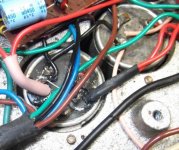
It was a pretty quick job and also the amplifier was heavy enough and the capacitor clip tight enough that there was no need to hold anything during drilling.
Ok I have some progress good and bad.
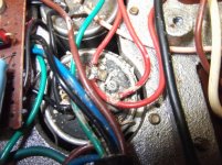
I have carefully changed all the coupling caps, replacing with restuffed metalpack caps. resistors out of spec have been replaced with Allen where possible.
Smoothing caps have been reformed as best as I can get 0.05v on 2v Range on DVM and 20 second to discharge caps. Capacitance reads within specs
After a lot of other checking I decided to power up with regulator valve only, no problems. I used a 100w bulb in line with the mains
I then replaced the other valves and applied audio in and attached speaker
turn off again and insert PX'4's
well large hum, followed by brightening of inline bulb
so quick switch off
tried one PX4, no hum no brightening
tried second, hum and lamp brightening
looks like one of the PX4's is duff!
audio is very low with the other installed. I haven't run it long like this.
I have a few questions if possible..
Is there any way of testing a PX4 without a dedicated valve tester
Is there another reason why a PX4' would cause this loud hum and current draw, other than being faulty
cheers
just as an update. Both vales were found to be faulty. One had a weld break and the other does not conduct. 2 new matched valves later and the amps is working. I am reading 350v from anode to chassis. Is this ok, I read max is 300 but I may be misunderstanding this. The amps sounds amazin, with a tiny bit of earth hum,may be the 2 pin plug
I put a 10k resistor on each anode to output tranny and measured 250v, so that's 25mA each valve.
I put a 10k resistor on each anode to output tranny and measured 250v, so that's 25mA each valve.
- Status
- Not open for further replies.
- Home
- Amplifiers
- Tubes / Valves
- Got some PX4 valves from an old radiogram