For any new Technology, they are not enough only subjective approvals from auditions.
The need for mathematical substantiation (proof) is crucial.
If there are the expected (good) results also from Measurements - only then we can be secure and peace of mind.
Please for your comments is this important and necessery or not - while I prepare the publication.
The need for mathematical substantiation (proof) is crucial.
If there are the expected (good) results also from Measurements - only then we can be secure and peace of mind.
Please for your comments is this important and necessery or not - while I prepare the publication.
Please let us know what you' ve come up with, but do not forget to include the drivers' individual SPL in the equation. The very reason active-subtractive, just like first order, rarely works with real drivers, is the intrinsic 2-order roll off of drivers: they are actually bandpass devices.
The analysis of John Kreskovsky will get you close:
https://pearl-hifi.com/06_Lit_Archive/14_Books_Tech_Papers/Kreskovsky_John/Crossed%20Over%20Speaker%20Transient%20Analysis.pdf
Or as a backup of his original website:
Speaaker Transient Analysis
https://pearl-hifi.com/06_Lit_Archive/14_Books_Tech_Papers/Kreskovsky_John/Crossed%20Over%20Speaker%20Transient%20Analysis.pdf
Or as a backup of his original website:
Speaaker Transient Analysis
Dear Boden and Wesayso, thank you for your attention!
The technology I use "requires" drivers with relatively flat frequency response and above all well aligned impedance and other condition. The research of Kreskovsky and all others - were a major stimulus for me.
I found two "unique" solutions for a good Step Response - one is with active crossovers.
Please share your achievements at this time - i am preparing my post.
Don't worry, I won't, I just remembered seeing his work on this subject and the observations he posted on this forum.
I did read his "Duelund and beyond" paper with some curiosity after finding the original Duelund paper.
I did read his "Duelund and beyond" paper with some curiosity after finding the original Duelund paper.
To the OP: Does your solution offer a transient improved response (like the usual time-aligned crossovers) or even a transient accurate one ?
Regards
Charles
Regards
Charles
Hi Charles,
I have been following your posts for years, and recently I am been a member of the forum. I will be happy to share and comment on all those who believe that good TIME parameters are important. Concepts such as: transient accurate, time-aligned, coherent phase, good transient, good Step Response are close in meaning. But if we study only the phase drawn by the frequency response measured with a noise generator or a slow sweep
- we can be deceived and get into naive abuse.
Best Regards
Boyko
Please share your achievements at this time - i am preparing my post.
I cheat 😀: https://www.diyaudio.com/forums/full-range/242171-towers-25-driver-range-line-array-167.html#post4579130

... but didn't use crossovers for that one.
Yes, with FIR -correction and -crossovers everything is possible. And the measurements of your system look exceptionally good.
The difficulties start when someone is trying the bulid transient-perfect crossovers in analog fashion.
My current crossover isn't transient perfect but it is better than most analog crossovers regarding group-delay distortion. I have a crossover frequency of 650 Hz and the group delay is flat and non-peaking. Its highest GD value is half of that of an LR 4 with the same x-over frequency. GD wise it behaves like a 2nd order allpass with a Q value of 0.5 and a pole frequency of 1.4 kHz.
Regards
Charles
Regards
Charles
Yes, without FIR -correction!
Transient-perfect crossovers in analog fashion - ONLY!!
Meyer has done the best job of that, staying active analog, that i know of....
Although i've heard rumor that even they are turning to FIR for certain speaker processing tasks.
John did good work on this, and at the time many thought it was going to be much more than it turned out to be.. but we wouldn't have been so sure without...Wesayso, I would not invest too much time trying to figure out Kreskovsky's paper.
Steen Duelund's paper also discusses this goal.
https://duelundaudio.com/wp-content/uploads/sites/3621/2013/12/duelund-filter.pdf
I wanted to make RS28F-RS180P-B80 as Hole Filler 3-way
but never got to work fully as it requires wide band drivers and all drivers have to be well behaved. Something like a Scan Speak 10F would be perfect for the hole filler.
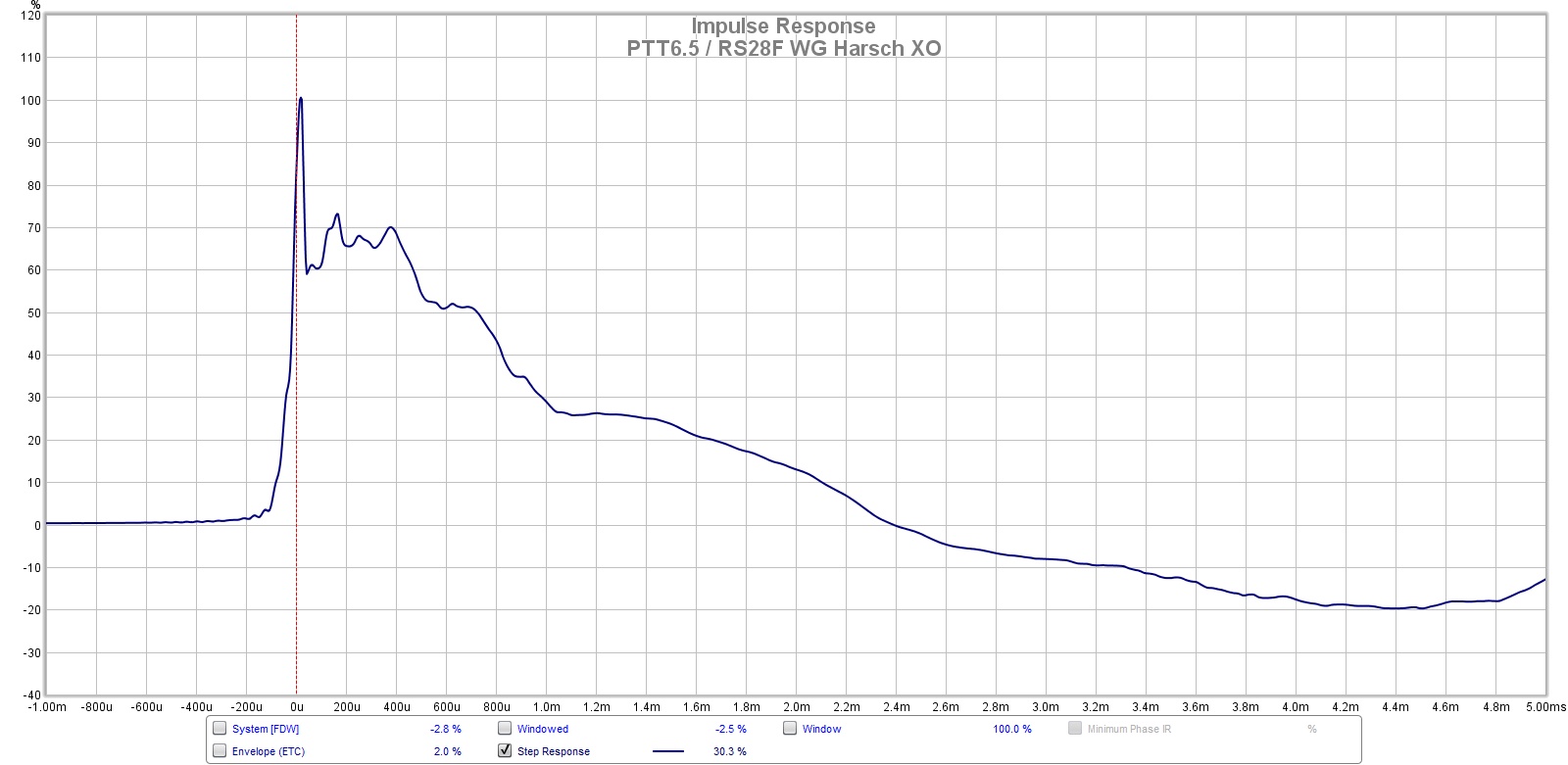
I was able to get a pretty good step response with what appears to be a passive Harsch XO using a waveguide for proper setback of the tweeter and a higher crossvover frequency.
XO schematic:
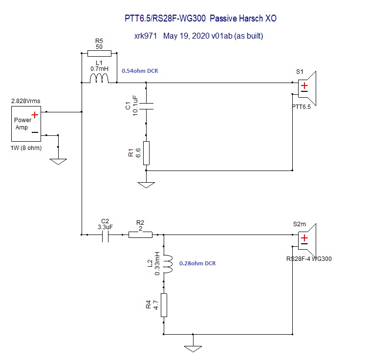
Simple Passive Harsch XO Using PTT6.5 and RS28F in a Waveguide
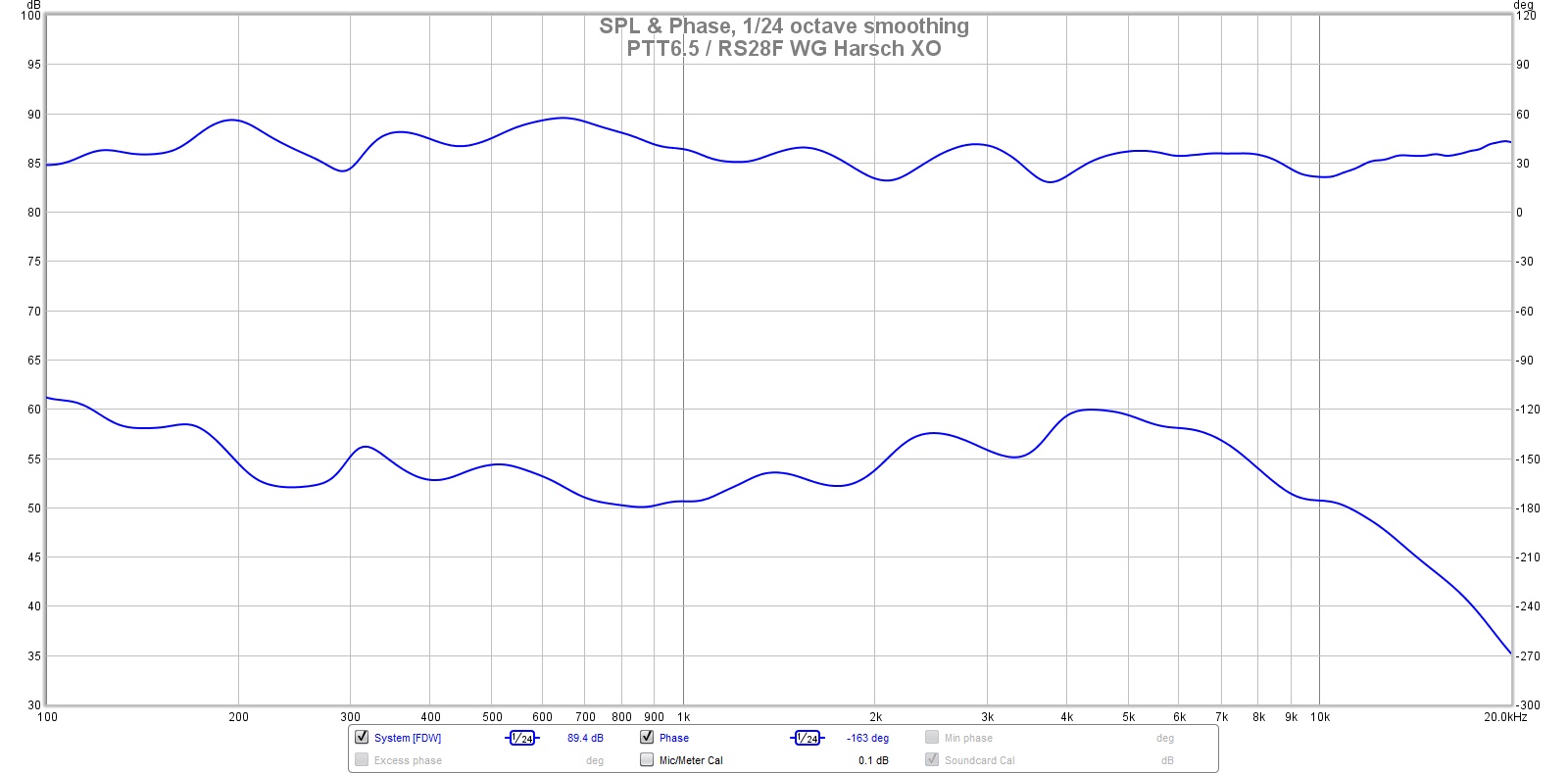
A conventional Harsch XO is usually only implemented with active or DSP since it requires large time delays. However, with the waveguide and a 3.5kHz XO frequency, I was able to do it passively. Basically a 4th order woofer low pass and a 2nd order tweeter high pass that meets a certain criterion for delay (delay must be 1/2 of the duration of the inverse of the XO freq). The tell-tale sign that it is a Harsch is that the combined woofer+tweeter has a slight dip below the raw woofer to the left of the XO point, and the phase has about a 55deg bump from flat near the XO frequency. Although my phase plot does not have the bump, it is realtively flat overall +/-5 deg over the audio band of interest.
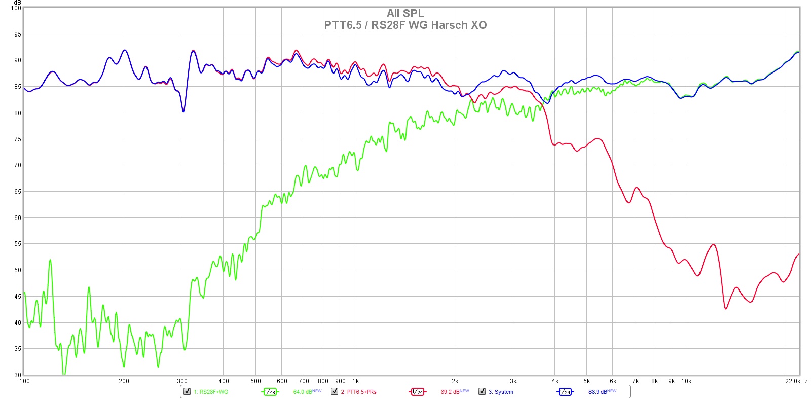
Here is the measured XO curve:
Measured response and phase:
Measured step response:
https://duelundaudio.com/wp-content/uploads/sites/3621/2013/12/duelund-filter.pdf
I wanted to make RS28F-RS180P-B80 as Hole Filler 3-way
but never got to work fully as it requires wide band drivers and all drivers have to be well behaved. Something like a Scan Speak 10F would be perfect for the hole filler.
I was able to get a pretty good step response with what appears to be a passive Harsch XO using a waveguide for proper setback of the tweeter and a higher crossvover frequency.
XO schematic:
Simple Passive Harsch XO Using PTT6.5 and RS28F in a Waveguide
A conventional Harsch XO is usually only implemented with active or DSP since it requires large time delays. However, with the waveguide and a 3.5kHz XO frequency, I was able to do it passively. Basically a 4th order woofer low pass and a 2nd order tweeter high pass that meets a certain criterion for delay (delay must be 1/2 of the duration of the inverse of the XO freq). The tell-tale sign that it is a Harsch is that the combined woofer+tweeter has a slight dip below the raw woofer to the left of the XO point, and the phase has about a 55deg bump from flat near the XO frequency. Although my phase plot does not have the bump, it is realtively flat overall +/-5 deg over the audio band of interest.
Here is the measured XO curve:
Measured response and phase:
Measured step response:
Last edited:
Wesayso,
Although I'm a fan of two or three way speakers - your work is huge!
Congratulations, bravo!
Although I'm a fan of two or three way speakers - your work is huge!
Congratulations, bravo!
Samuel Harsch filters have no phase-time deviations if the high frequency driver is with
suitable waveguide. They are dangerous for loud listening - because the slopes are smaller than the first order.
suitable waveguide. They are dangerous for loud listening - because the slopes are smaller than the first order.
They are dangerous for loud listening - because the slopes are smaller than the first order.
In his proposal that he presented at an AES meeting he suggested 2nd order HP for the tweeter. Ok if you are close to your tweeters cutoff you would have to try to achieve 2nd order acoustic which wouldn't give a lot of protection. If you are far enough from the tweeters cutoff things look differently however.
Regards
Charles
- Home
- Loudspeakers
- Multi-Way
- Good Step Response with passive filters higher than first order