If not all reactive elements are "decorated" with resistors -
then we can move on to the second order.
then we can move on to the second order.
Samuel Harsch filters have no phase-time deviations if the high frequency driver is with
suitable waveguide. They are dangerous for loud listening - because the slopes are smaller than the first order.
How is 2nd order high pass for a dome tweeter or any tweeter, dangerous - especially at 3.5kHz like I have done?
Also, Linkwitz Riley 2nd order is very popular and no one talks about it being "dangerous".
Step Response, when will you post some technical details of what you propose? Is there any similarity with what Duelund has described in his paper?
Linkwitz Riley 2nd order is reality a second order.
But with the "excess" resistors in the filter on Harsch - he leans towards the low first order.
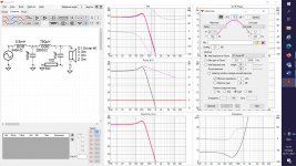
This can be seen from a simulation with Multisim, Orcad or Altium.
Be a little patient while i preparing the post.
Because it's easier to invent Technology - than to describe and explain it! ����
But with the "excess" resistors in the filter on Harsch - he leans towards the low first order.
This can be seen from a simulation with Multisim, Orcad or Altium.
Be a little patient while i preparing the post.
Because it's easier to invent Technology - than to describe and explain it! ����
While it's not how I do things myself (not a reflection, just a statement of different priorities), eyeballing XRK's measured FR graphs shows a progressive rate slope accelerating from an initial 1st order at the XO frequency & the first octave of rolloff, to 2nd order & increasing (as you would expect) below that.
Wesayso,
Although I'm a fan of two or three way speakers - your work is huge!
Congratulations, bravo!
Thanks for the compliment, looking forward to reading your theory/post.
GOOD STEP RESPONSE
Good Step Response
A brief overview
...In the beginning was the… Idea.
The idea to restore the input signal phase-temporally, i.e. transient processes as “live”.
The eternal problem in constructing speakers is to make all components of the sound spectrum arrive at the listener’s ear at the same time or without delay between speakers.
Needless to say, filters are the brain and heart of speakers. As music evolves over time - we accept the parameters of Time as Suprime (highest important) than the STATIONARY frequency response.
This does not mean a limited and curved frequency response.
Proper full band signal reproduction requires all spectral components to be arranged with their exact amplitudes, which are constantly changing and are crucially dependent on the time domain.
The idea arose when as a musician (bass guitar) and as a sound director I listened to the general (mixed) sound from two-way and three-way speakers. There were no micro details, natural timbres, attack (increase) and decrease (fading reverberation) in time and space. There was no sense of a specific scene and no directives from individual instruments and vocals. The big ambition for me was after reading a study by R. Heiser and later Lipshitz, Vanderkooy, Kreskovsky.
F. Brooke's articles "Le filtre ideal" in L'AUDIOPHILE was no small stimulus and last but not least. The Loudspeaker Cookbook by V. Dickason has been my desktop reading for many years. Of course - the biggest challenge was the "hidden" delays (resonances) of the filters, higher than the first order.
This technology is very important, but it is not a wizard panacea for all other
problems and omissions.
We can not talk about good Timing - if there is a band with reverse polarity.
But it is not superfluous to know - before measuring the impedances and frequency responses for the future project, an appropriate selection of speakers must be made, incl. preliminary solution for optimal shear frequencies. Ie - together with the choice we specify: The self resonance of each high frequency(offcourse and middle driver) must be one / two octaves farther (down) from the filter frequency.
The rule is general alignment according to the quietest speaker. Ensuring flat
(constant) impedance for each filter - too. Working with a simulation program is essential (help).
Pre-planning the possibility for precise movement between the centers of the adjacent drivers (speakers) through separate enclosures (boxes) - mandatory!
Precise observance of results (values) from the filters, including displacement (delay) - too!
If we get as close as possible to a better Step Response - this would be adequateto the original input signal without time distortion. And then after the obtained accuracy, precision and fidelity can be speaks of musicality and emotionality, if contained in the RECORD!
Over the years we have tried different solutions to the problem - with the classic First Order, incl. serial filter, Baekgaard (Christensen), Cauer (elliptical) filters, combinations Bessel (Spica), Z. Linkwitz, Elipson , Urei Time-Align crossover, JMLC, Duelund, Bodzio(SoundEasy/Ultimate Equalizer, Isaac MCN, Jeff Bagby's Software, LinearX LEAP(in memoriam).........they all had their pros and cons.
The first order is "lost" in the driver's frequency response curve. The desired filters must also be dominant in relation to the speaker's own slope.
The main goal for me was - to fill well the transient response, flat plateau without shaking(approximately+/-5%) and maximum linear frequency response+/-0.7db!
I have to admit that there is a good solution with DSP, but not for those pro
users and audiophiles - who want an analog path from input to output.
Attention!
Mandatory recommendation!
The resonances of the selected high frequency drivers should be about two octaves down from the crossover frequency !! For example, Illuminator D3004 /
604010 with a resonance of 450 Hz will work normally at a filter frequency of 1800 Hz. Large professional drivers with a resonance of about 350 Hz - perhaps at a filter frequency of about 750 Hz (special cases with Altec 288, TAD 4001/4003, Radian 950/951).
Projects for Excellent Step Response will be free for homemade DIY.
This product is protected by intellectual property law. All rights reserved.


THANK YOU FOR WAITING!
ENJOY!
Good Step Response
A brief overview
...In the beginning was the… Idea.
The idea to restore the input signal phase-temporally, i.e. transient processes as “live”.
The eternal problem in constructing speakers is to make all components of the sound spectrum arrive at the listener’s ear at the same time or without delay between speakers.
Needless to say, filters are the brain and heart of speakers. As music evolves over time - we accept the parameters of Time as Suprime (highest important) than the STATIONARY frequency response.
This does not mean a limited and curved frequency response.
Proper full band signal reproduction requires all spectral components to be arranged with their exact amplitudes, which are constantly changing and are crucially dependent on the time domain.
The idea arose when as a musician (bass guitar) and as a sound director I listened to the general (mixed) sound from two-way and three-way speakers. There were no micro details, natural timbres, attack (increase) and decrease (fading reverberation) in time and space. There was no sense of a specific scene and no directives from individual instruments and vocals. The big ambition for me was after reading a study by R. Heiser and later Lipshitz, Vanderkooy, Kreskovsky.
F. Brooke's articles "Le filtre ideal" in L'AUDIOPHILE was no small stimulus and last but not least. The Loudspeaker Cookbook by V. Dickason has been my desktop reading for many years. Of course - the biggest challenge was the "hidden" delays (resonances) of the filters, higher than the first order.
This technology is very important, but it is not a wizard panacea for all other
problems and omissions.
We can not talk about good Timing - if there is a band with reverse polarity.
But it is not superfluous to know - before measuring the impedances and frequency responses for the future project, an appropriate selection of speakers must be made, incl. preliminary solution for optimal shear frequencies. Ie - together with the choice we specify: The self resonance of each high frequency(offcourse and middle driver) must be one / two octaves farther (down) from the filter frequency.
The rule is general alignment according to the quietest speaker. Ensuring flat
(constant) impedance for each filter - too. Working with a simulation program is essential (help).
Pre-planning the possibility for precise movement between the centers of the adjacent drivers (speakers) through separate enclosures (boxes) - mandatory!
Precise observance of results (values) from the filters, including displacement (delay) - too!
If we get as close as possible to a better Step Response - this would be adequateto the original input signal without time distortion. And then after the obtained accuracy, precision and fidelity can be speaks of musicality and emotionality, if contained in the RECORD!
Over the years we have tried different solutions to the problem - with the classic First Order, incl. serial filter, Baekgaard (Christensen), Cauer (elliptical) filters, combinations Bessel (Spica), Z. Linkwitz, Elipson , Urei Time-Align crossover, JMLC, Duelund, Bodzio(SoundEasy/Ultimate Equalizer, Isaac MCN, Jeff Bagby's Software, LinearX LEAP(in memoriam).........they all had their pros and cons.
The first order is "lost" in the driver's frequency response curve. The desired filters must also be dominant in relation to the speaker's own slope.
The main goal for me was - to fill well the transient response, flat plateau without shaking(approximately+/-5%) and maximum linear frequency response+/-0.7db!
I have to admit that there is a good solution with DSP, but not for those pro
users and audiophiles - who want an analog path from input to output.
Attention!
Mandatory recommendation!
The resonances of the selected high frequency drivers should be about two octaves down from the crossover frequency !! For example, Illuminator D3004 /
604010 with a resonance of 450 Hz will work normally at a filter frequency of 1800 Hz. Large professional drivers with a resonance of about 350 Hz - perhaps at a filter frequency of about 750 Hz (special cases with Altec 288, TAD 4001/4003, Radian 950/951).
Projects for Excellent Step Response will be free for homemade DIY.
This product is protected by intellectual property law. All rights reserved.
THANK YOU FOR WAITING!
ENJOY!
When the important thing in the project is Alignment Time and selection of suitable drivers with relatively flat frequency response - is not that enough?...
P.S.If the individual slope of the driver is close
to cut frequency - of course it incl. in "simple" arithmetic.
I can send a total frequency response on the speaker box.
to cut frequency - of course it incl. in "simple" arithmetic.
I can send a total frequency response on the speaker box.
Still I find the individual slopes relevant, so -for me at least- the total freq. response is not enough. But in case you are reluctant to show these: fine. This is your thread after al.
I want to show them, but it will take a long time to search the "seas" of files. Very close (similar) to their original graphics:
Audax PR240M6
Supravox 165 GMF
HiVi Swan RT2Pro
Audax PR240M6
Supravox 165 GMF
HiVi Swan RT2Pro
This is indeed a nice step resonse but it has still some of that "leading midrange" that other solutions of transient improved crossovers (using "normal" filters plus delay) also show.
One of the topologies with reduced group delay distortion that I tried was using the same type of lowpass as you do (1st order lowpass and 2nd order Butterworth lowpass with equal pole/cutoff frequencies) but also its mirror image for the high pass. One has to delay the tweeter as well in order to achieve a maximally flat amlitude response. Because I use a horn tweeter this was easily achieved.
The suggestion to use such a crossover for direct radiator / horn combos came from John K AFAIK.
Regards
Charles
The woofer lowpass is (electric) second order with a Q of 1.2 and F-3= 260 Hz. I am curious to learn whether that electric transfer, loaded with the "real" woofer translates into (pseudo) second or third order acoustic.
Are you talking about the schematic that the TO posted ?
Every lowpass shown there is definitely third order. Combined with a driver's acoustic response this results in a higher order transfer function. But because per design rule the cutoff frequency of the lowpass is much lower than the driver's intrinsic acoustic lowpass cutoff the electric part of the transfer function dominates. It woud also be possible to build an electric filter that achieves a good approximation of an acoustic lowpass of third order together with the driver's acoustic rolloff relaxing the demand on the driver's upper cutoff frequency.
This is most easily achieved when the elctric filter order of the crossover is higher than the order of the acoustic rolloff. It is of course also possible to achieve this when both orders are the same but that would mean more spectral content reaching the driver where it is not working properly anymore. With active filters it is even posssible to achieve a combined response that is of lower order than the intrinsic rolloff of the driver but this can get dangerous.
Regards
Charles
Last edited:
Tomorrow I will check again whether I made a mistake. Simply sim the woofer lowpass circuit in Vituixcad, then manipulate the target curve until you have a fit.
Did you simulate and fit both - amplitude and phase ? Since the circuit itself is 3rd order the response definitely must be third order as well.
Regards
Charles
Regards
Charles
Phase is a function of amplitude in analogue filtering as per Hilbert/Bode.
Yes - it definitely is (for minimum phase networks to be more exact). But only comparing amplitude response curves on a dB scale can sometimes lead to wrong conclusions.
BTW: What is the impedance of the driver that you use for simulating ?
From the formulae he is showing us all crossover filter sections should have the same pole frequency. A first order lowpass followed by a 2nd order Butterworth lowpass with the same pole frequency. The highpass has the same pole frequency but a Q of 0.42. This means both branches cross at approximatley -6dB. So the -3dB point of any crossover branch is not that relevant.
Regards
Charles
If you are willing to consider active, the following paper on subtractive crossovers, by John Kreskovsky, is must reading. It presents interesting advancements over the usual subtractive approach.
A New High Slope, Linear Phase Crossover Using the Subtractive Delayed Approach - PDF Free Download
A New High Slope, Linear Phase Crossover Using the Subtractive Delayed Approach - PDF Free Download
- Home
- Loudspeakers
- Multi-Way
- Good Step Response with passive filters higher than first order