The ESR of a cartridge is just the resistance, and its just the resistance that contributes Johnson noise. The inductive contribution to impedance doesn't generate noise. Of course current noise can translate reactive impedance to voltage noise, but its series resistance that creates Johnson noise.You seem to assume a constant effective series resistance of about 1 kohm, but the ESR of a Shure V15-III increases from 1.85 kohm at 2 kHz to 30.1 kohm at 20 kHz, according to measurements of an acquaintance of mine. Anyway, a 47 kohm series resistor is indeed far from optimal for noise.
Is there anything to be said against building the tube circuit in several stages and not putting the EQ in the first stage right away?

We could save the passive 75µsec TP1 and implement a classic PID-Design.
Does that work with tubes? I don't think so, too bad 😢.
We could save the passive 75µsec TP1 and implement a classic PID-Design.
Does that work with tubes? I don't think so, too bad 😢.
The ESR of a cartridge is just the resistance, and its just the resistance that contributes Johnson noise. The inductive contribution to impedance doesn't generate noise. Of course current noise can translate reactive impedance to voltage noise, but its series resistance that creates Johnson noise.
Yes, of course, but the real part of the impedance of a real-life cartridge is far from constant.

Suppose you wanted to implement chip_mk's original idea from post #24 and active RIAA correction via shunt feedback in the second stage, while using only a single triode in each stage. You would then end up with something like the upper schematic of these three:

When you simply replace each resistor and each capacitor with an ideal one and each triode with the usual small-signal models, you end up with the middle schematic. It's ninth order (there are ten capacitors plus zero inductors, but four of the capacitors are in a loop, reducing the order to nine) and everything influences everything, making it impractical to use this schematic for hand calculations.
Assuming that the cathode decoupling capacitors can be made so large that their effect can be neglected and that the internal capacitances of the second valve are small enough not to do much harm, you end up with the third schematic, which is still fifth order with everything influencing everything.
Assuming that the AC coupling capacitors C3 and C6 will also be made big enough, which is an assumption that is not always met, that the input of the second stage is not an ideal virtual ground, but close enough to be modelled as having a constant input impedance Zst2 for frequencies in the vicinity of 2122 Hz, and hoping that C2 won't affect the pole of the second stage much as 75 us << 3.18 ms, the circuit can be split into these two more manageable parts:

To be continued when I have calculated the transfers and impedances.
When you simply replace each resistor and each capacitor with an ideal one and each triode with the usual small-signal models, you end up with the middle schematic. It's ninth order (there are ten capacitors plus zero inductors, but four of the capacitors are in a loop, reducing the order to nine) and everything influences everything, making it impractical to use this schematic for hand calculations.
Assuming that the cathode decoupling capacitors can be made so large that their effect can be neglected and that the internal capacitances of the second valve are small enough not to do much harm, you end up with the third schematic, which is still fifth order with everything influencing everything.
Assuming that the AC coupling capacitors C3 and C6 will also be made big enough, which is an assumption that is not always met, that the input of the second stage is not an ideal virtual ground, but close enough to be modelled as having a constant input impedance Zst2 for frequencies in the vicinity of 2122 Hz, and hoping that C2 won't affect the pole of the second stage much as 75 us << 3.18 ms, the circuit can be split into these two more manageable parts:
To be continued when I have calculated the transfers and impedances.
Yes - agreeYes, but the shunt feedback phono topology is flawed nonetheless and best avoided unless you have a liquid-helium cooled 47k resistor to hand!
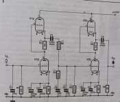
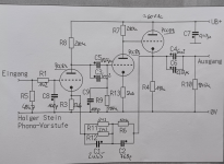
In 1995, a friend and I set up the SRPP variant with great success. In the early 1990s, Holger Stein and the PCC88 emerged on the German DIY scene, and the magazine "Klang und Ton", headed by speaker builder Bernd Timmermanns, praised Holger Stein highly at that time.
To complete the collection of possible dimensions and topologies, I am attaching photos. Ultimately, you are always faced with a single decision.
To complete the collection of possible dimensions and topologies, I am attaching photos. Ultimately, you are always faced with a single decision.
Attachments


In the last schematic of post #44, with the split parts, R4B should simply be R4, otherwise the interaction between the output impedance of the first and the input impedance of the second stage is counted twice.
Analysis of the first stage of post #44, the second is still to be done. When input capacitance is not that critical while noise is, you could add an RC parallel network (with a DC blocker capacitor in series) with R(C + cga1) = 75 us between anode and grid of the first valve to make an electrically cold input resistance. I haven't looked into that, though.


I don't think core losses are going to increase the impedance though.Yes, of course, but the real part of the impedance of a real-life cartridge is far from constant.
Thank you Bonsai. The second stage gets rather messy for finite gm2...
I've used a slightly different approximation than I wrote before: I only assume a more or less constant second-stage input impedance for calculating C2 and incorporate the first stage's impedance with neglected C2 when calculating the values for the second stage.


Next step is to find some procedure to calculate the component values from this. Maybe one can use the limit for infinite transconductance first and use the full equations to find some kind of correction term?
I've used a slightly different approximation than I wrote before: I only assume a more or less constant second-stage input impedance for calculating C2 and incorporate the first stage's impedance with neglected C2 when calculating the values for the second stage.
Next step is to find some procedure to calculate the component values from this. Maybe one can use the limit for infinite transconductance first and use the full equations to find some kind of correction term?
I don't think core losses are going to increase the impedance though.
My discussion with you was about the real part, and according to Richard Visee's measurements, the real part of the impedance increases quite a bit. See "Noise and moving-magnet cartridges", Electronics World October 2003, pages 38...43, https://worldradiohistory.com/UK/Wireless-World/00s/Electronics-World-2003-10-S-OCR.pdf Mind you, Electronics World drew one of the sections of the gain switch in the wrong state in figure 5, and I mixed up the terms spectral density and power spectral density.
Core losses reduce the quality factor, so they either have to increase the real part or reduce the imaginary part of the impedance, or both. Apparently they mostly do the first.
By the way, as you probably know, connecting a large resistor in parallel with an inductor usually leads to an increase of the real part of the impedance. That's easy to see with an ideal inductor.
Last edited:
Thank you Marcel - for your huge commitment,
especially because rongon could perhaps have done it himself. That was once again very selfless of you.
Great work.
🙂
especially because rongon could perhaps have done it himself. That was once again very selfless of you.
Great work.
🙂
It turns out there was one resistor missing from the netlist I put into the program I used to check whether the poles ended up where I had calculated them to end up. That is, the calculation was fine, the check was wrong. See the attachment for an update.
@rongon I think this is a feasible way to make a reasonably simple valve phono amplifier with a small input capacitance. The RIAA correction accuracy will not be spectacular because of the sensitivity to the transconductances and internal resistances of the valves, but that's the price you pay for simple circuits (that and rather complicated calculations). See section 4 for an example.
@rongon I think this is a feasible way to make a reasonably simple valve phono amplifier with a small input capacitance. The RIAA correction accuracy will not be spectacular because of the sensitivity to the transconductances and internal resistances of the valves, but that's the price you pay for simple circuits (that and rather complicated calculations). See section 4 for an example.
Attachments
Last edited:
- Home
- Source & Line
- Analogue Source
- Good resource for learning how to figure RIAA EQ in a feedback loop (Active RIAA)?