Hmmm... That looks like it would be a problem. Would that cause a droop in response >10kHz?
The other problem is that high value R2 is in series with the input, so whatever noise that resistor makes will be injected right at the front of the circuit. That's probably not a good idea either.
The other problem is that high value R2 is in series with the input, so whatever noise that resistor makes will be injected right at the front of the circuit. That's probably not a good idea either.
For the original poster's question: studying this may be of help to explain the principles (i assume you are already comfortable computing gain of your desired tube gain stages).
https://www.andyc.diy-audio-engineering.org/phono-preamp/index.html
https://www.andyc.diy-audio-engineering.org/phono-preamp/index.html
If 2122Hz pole is implemented as RC anode load in the first stage, gain at HF will be low. Consequently, multiplication factor of Miller C will be low, avoiding unwanted capacitive load of cartridge.
Good point. Any remaining Miller effect will mostly add conductance for frequencies above 2122 Hz, so you could even correct for it with a slightly larger input termination resistor.
You can take a look at the resource below. I don’t know enough about tubes to comment on the feedback network loading the tube stages and or available loop gains which tend to be lower than opamp based designs.
However, the spreadsheet will allow you to calculate the RIAA network values using the Lipshitz equations for all-active RIAA EQ. Separately, in the article, you can read about the Baxandall active/passive EQ which is easy to calculate but might not have the HF headroom of the all active approach. However, this might be better suited to tubes.
https://hifisonix.com/technical/riaa-phono-equalizer-amplifiers/
At the beginning you asked for a book that could help you with your ideas and projects,
VALVE AMPLIFIERS
Morgan Jones
ISBN 978-0-08-096640-3
we already had that, but if you can read German, then
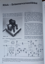
"Audio- und Gitarrenschaltungen mit Röhren
von
R. zur Linde
ISBN 3-921608-69-4 (Elektor-Verlag)"
this comprehensive book would be something for you, in particular.
Good luck with your attempts,
HBt.
This would be at the cost of a heavy reactive load to that (triode) stage, so isn't optimum from a distortion, or from a slewing, standpoint. Maybe signal is small enough that distortion doesn't matter, but.If 2122Hz pole is implemented as RC anode load in the first stage, gain at HF will be low. Consequently, multiplication factor of Miller C will be low, avoiding unwanted capacitive load of cartridge.
I'm puzzled that the classic long-loop all-active RIAA feedback has become unfashionable when we now have tools to do the (serious) calculations needed to get the Rs and Cs right. Except for the difficulties of the calculations, what faults did the classic way have? DC heaters assumed.
All good fortune,
Chris
Alternatively, anode loaded with combination of two resistors and one capacitor implementing 50Hz pole and 500Hz null would ensure less reactive anode load. In addition, since HF gain would be 10x (20dB) lower than LF gain it would reduce Miller's capacitance in same proportion. For 12AX7 that would be <15-20pF additional C seen by cartridge.This would be at the cost of a heavy reactive load to that (triode) stage, so isn't optimum from a distortion, or from a slewing, standpoint. Maybe signal is small enough that distortion doesn't matter, but.
Sorry, I did simplify down to basic triode common cathode stages.These circuits are very different from what you described in post #1.
I have built a preamp with a hybrid cascode as the first stage (6N6P on top, LSK170 on bottom), but with passive EQ.
For this exercise, the thing I'm most concerned with is implementing the 50Hz-500Hz network via shunt NFB in the first stage plate circuit. The main reason would be to reduce Miller C and THD.
Now I see what you have in mind, in principle something like this here - but that is unorthodox, with R1=47kOhm or 150kOhm 😉 .

Naturally with electron tubes and not with semiconductors as an amplifying element.
Good luck,
HBt.
Naturally with electron tubes and not with semiconductors as an amplifying element.
Good luck,
HBt.
150k 😉Now I see what you have in mind, in principle something like this here - but that is unorthodox, with R1=47kOhm or 150kOhm 😉 .
View attachment 1264506
Naturally with electron tubes and not with semiconductors as an amplifying element.
Good luck,
HBt.
[Mark, it's a dig at a certain gentleman on the forum who insists 150k is better than 47k]
Yes, but the shunt feedback phono topology is flawed nonetheless and best avoided unless you have a liquid-helium cooled 47k resistor to hand!
Mark,
that's all true, but apparently that's what 'rongon' wants to implement.
Feel free to point this misdeed out to him. (I just wanted to wave the fence post - and for a better understanding: give a simple principle schematic, to overview!)
Regards,
HBt.
that's all true, but apparently that's what 'rongon' wants to implement.
Feel free to point this misdeed out to him. (I just wanted to wave the fence post - and for a better understanding: give a simple principle schematic, to overview!)
Regards,
HBt.
Last edited:
150k in series with the input is 50nV/√Hz, 47k is 28nV/√Hz, compared to the Johnson noise of a typical cartridge of 4nV/√Hz.
Basically "series resistance" and "preamplifier" don't sit well together!
You seem to assume a constant effective series resistance of about 1 kohm, but the ESR of a Shure V15-III increases from 1.85 kohm at 2 kHz to 30.1 kohm at 20 kHz, according to measurements of an acquaintance of mine. Anyway, a 47 kohm series resistor is indeed far from optimal for noise.
This. You want to put the gain first without adding series resistance.Basically "series resistance" and "preamplifier" don't sit well together!
Ed
Now I see what you have in mind, in principle something like this here - but that is unorthodox, with R1=47kOhm or 150kOhm.
See post #2.
OK, thank you for bearing with me. Yes, I think this is not a good idea. The series resistance is a no-no for a low noise preamp. Also, the source resistance will mess with the gain inside the feedback loop. which is certainly not optimal. This type of thing is best done with op-amps, not tubes.
- Home
- Source & Line
- Analogue Source
- Good resource for learning how to figure RIAA EQ in a feedback loop (Active RIAA)?


