I've been casting around looking for a source that's easy enough for me to understand but detailed and complete enough to point me in the right direction.
What I'd like to do is make a tube phono stage with the first stage being a hybrid cascode (triode on top, JFET on bottom), then the 2122Hz low pass done passively, and then a triode second stage with plate-grid (shunt) NFB with the 50Hz-500Hz shelving EQ done actively (in the FB loop).
The problem is that I don't know how to figure the values for the passive components inside the shunt FB loop of a typical triode (I'm thinking 6DJ8 or similar).
Can anyone recommend a book that goes through the design process for this kind of thing?
Thanks.
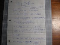
Here's what the calculation for a perfect, ideal amplifier looks like.
Including the imperfect tube's characteristics is much more complex to calculate.
Note there are 5 variables and three equations, so two variables must be carefully assigned
values, in order to solve for the other three variables and get acceptable results.
A0 would be 1000 in modern phono preamps, and C1 would be typically 1 to 3 nF.
The R3 will also present a load to the first stage, and to the passive 75uS RC network,
so it will enter into that calculation as well.
In practice, this won't work for a single tube stage, even a pentode, due to inadequate gain in the tube.
Quad used a different circuit in their single tube phono preamp, but even then, it ran open loop at low frequencies.
A two tube, all passive RIAA (with tube/network/tube) is the best approach for tubes.
Attachments

All passive RIAA is the best approach for tubes.
Either that or put more than just one valve in the amplifier that you apply the active correction to.
I was thinking of trying to do something like an ESP Project-06 with tubes instead of opamps.
https://sound-au.com/project06.htm
![p06-f1[1].gif](https://www.diyaudio.com/community/attachments/p06-f1-1-gif.1263857/ "p06-f1[1].gif")
I built one up on one of Rod's PCBs and was very pleasantly surprised at the sound. I was thinking it might work well with a 12AX7 for the first stage and a 6DJ8 for the second (output) stage. I suppose I could just scale the values of the Rs and Cs for higher impedance.
Maybe use 12AX7s with small MOSFET source followers after each triode, to drive the feedback loop (first stage) and output (second stage).
https://sound-au.com/project06.htm
I built one up on one of Rod's PCBs and was very pleasantly surprised at the sound. I was thinking it might work well with a 12AX7 for the first stage and a 6DJ8 for the second (output) stage. I suppose I could just scale the values of the Rs and Cs for higher impedance.
Maybe use 12AX7s with small MOSFET source followers after each triode, to drive the feedback loop (first stage) and output (second stage).
You can't do that single tube first stage with tubes, because they don't have enough gain.
A phono stage needs around 40dB gain overall (x100) at 1kHz after feedback,
so there's needed around 60dB gain (x1000) at low frequencies, after feedback.
You can sorta do it with two tubes cascaded, with overall feedback to the first cathode,
but the response would still vary in the lower frequencies with tube variations.
I've been casting around looking for a source that's easy enough for me to understand but detailed and complete enough to point me in the right direction.
What I'd like to do is make a tube phono stage with the first stage being a hybrid cascode (triode on top, JFET on bottom), then the 2122Hz low pass done passively, and then a triode second stage with plate-grid (shunt) NFB with the 50Hz-500Hz shelving EQ done actively (in the FB loop).
The problem is that I don't know how to figure the values for the passive components inside the shunt FB loop of a typical triode (I'm thinking 6DJ8 or similar).
Can anyone recommend a book that goes through the design process for this kind of thing?
Thanks.
I don't know any book that goes through the design process of the exact circuit you are interested in, but a good textbook on linear electric network theory (a.k.a. circuit theory, although electric network theory is a slightly more generic term) should give you enough information to do and understand the kind of calculation rayma did, as well as similar calculations on more complicated networks. The notes my former network theory professor, professor Neerhoff, wrote were very good, but they were in Dutch and I don't think they were ever available in any normal book shop.
Years ago I tried to summarize it in the appendix of a Linear Audio article. The attachment is an adaptation of that. It's probably too condensed, but maybe it will be of some use anyway.
Attachments
I thought all the hip people did this by piece-wise convergence in LT Spice. You guys who want to actually understand/overstand/predict this are so Twentieth Century. And hopelessly over my head, although that's a low bar to set.
All good fortune,
Chris
All good fortune,
Chris
Off topic: I thought "overstand" was Rastafarian Jamaican English, is it also used in American English?
No, I'm just a big fan.
Peace, Jah!, Rastafari, Ever living, Ever peaceful, Ever sure,
Greetings in the name of the Lion of Judah,
Peace, Jah!, Rastafari, Ever living, Ever peaceful, Ever sure,
Greetings in the name of the Lion of Judah,
We better not continue this little off-topic discussion, considering the forum rules about religion...
I have definitely bit off more than I can chew.
Busted! Guilty as charged. But I'm working on it...
I thought all the hip people did this by piece-wise convergence in LT Spice
Busted! Guilty as charged. But I'm working on it...
Great summary Marcel. I would like to add this for the public, if filter is build as a negative feedback network around a gain block, the end result will be affected also by the transfer function of the gain block itself. If OLG is much higher than the CLG than the FB NW will dominate in the overall result. That's mostly the case with opamps with high OLG e.g. 120dB. So designer can concentrate only on FB NW design (RC network in most phono preamps).Years ago I tried to summarize it in the appendix of a Linear Audio article. The attachment is an adaptation of that. It's probably too condensed, but maybe it will be of some use anyway.
However, discrete designs tend to have much lower OLG. In that case one should take into account this (more strict) formula:
A = Ao / (1 + B * Ao)
Where A is the overall complex transfer function (RIAA preamp 🙂), Ao is the OLG transfer function, B (Greek beta) is the transfer func of the feedback network. When Ao is very high it'll tend to cancel in the above expression, so we get the simplified formula A = 1/B. Overall result (A) is inverse of FB NW (B).
This is what I got after copying the ESP circuit but with triodes, scaling the R and C values, and re-jiggering the values in LTspice to dial in the RIAA characteristic.

R14, R5, R4, C2 are the Rs and Cs for the active half of the RIAA (50Hz to 500Hz shelf).
R8 and C3 are the R and C for the 2122Hz roll-off.
Those values were not arrived at by doing the math. I cut-and-pasted values in LTspice until I got the RIAA characteristic as close to right as possible. It looks like this:

My reasoning for putting the active EQ (NFB) in the first stage is to set the 47k ohm input impedance and lower the Miller C to a very low value so it won't interact with Audio Technica MM cartridges (which like to see a total of only about 150pF input C).
Is this stupid?
R14, R5, R4, C2 are the Rs and Cs for the active half of the RIAA (50Hz to 500Hz shelf).
R8 and C3 are the R and C for the 2122Hz roll-off.
Those values were not arrived at by doing the math. I cut-and-pasted values in LTspice until I got the RIAA characteristic as close to right as possible. It looks like this:
My reasoning for putting the active EQ (NFB) in the first stage is to set the 47k ohm input impedance and lower the Miller C to a very low value so it won't interact with Audio Technica MM cartridges (which like to see a total of only about 150pF input C).
Is this stupid?
Here's a second stab at it, this time with two 12AX7s (no 6922 this time)...

The frequency response with inverse-RIAA looks like this (in simulation):

The simulation says this version has much lower THD, and higher gain too. Win-win.
The frequency response with inverse-RIAA looks like this (in simulation):
The simulation says this version has much lower THD, and higher gain too. Win-win.
- Home
- Source & Line
- Analogue Source
- Good resource for learning how to figure RIAA EQ in a feedback loop (Active RIAA)?