DcibeL said:am a computer nerd at heart, so sadly my source for my stereo is my computer.
Nothing wrong with that. I know people who have sold their CD players because the playing music off the hard disc is so much better than their modified CD players as the source.
Even some soundcards are beating some HiFi DACs, the new Creative X-Fi does sound quite good. It's crystaliser turns out to be quite good too 🙂 turns a dull sounding not so well recorded album into a better one, without adding nasties.
Christer said:Carlos,
what is the purpose of R6? I fail to see any reason for it.
When not connected to the next stage (ex: the amp), it provides a return path to ground.
carlosfm said:
When not connected to the next stage (ex: the amp), it provides a return path to ground.
Return path for what? The point that is grounded via R6 is already grounded via the much lower impedance path R5-R4-R3. If there were a coupling capacitor on the output, then there would be areason for R6
(although opinions might differ whether it were necessary). Not that R6 will do any harm, but it won't make any good either as far as I can see.
I'm sorry to stray off topic, but would anybody here use the AD8066 instead of the AD826 for CD output?
I've ordered my copy of "The Art of Electronics" by Paul Horowitz; Hardcover; so that I can begin to answer these questions better myself, btw.
However, if anybody could enlighten me, I would still be very much obliged.
Cheers.
I've ordered my copy of "The Art of Electronics" by Paul Horowitz; Hardcover; so that I can begin to answer these questions better myself, btw.
However, if anybody could enlighten me, I would still be very much obliged.
Cheers.
If the following amp is DC coupled, then R6 would be in parallel with the amps input resistor which may be a 47k.
I don't really know what the ramifications of this would be. But it might explain the odd effects I've encountered before.
One of my colleagues always uses an R6. He says 'it defines the load' and its effect with the following cable.
I don't really know what the ramifications of this would be. But it might explain the odd effects I've encountered before.
One of my colleagues always uses an R6. He says 'it defines the load' and its effect with the following cable.
ozone_stink said:I'm sorry to stray off topic, but would anybody here use the AD8066 instead of the AD826 for CD output?
If the output is at unity gain, had you considered the BUF04, or what it's been replaced with? We've had good results. And it can be in a sallen and key filter too. And I think I might be right in saying that due to in not being and op-amp as such, with no external feedback connection, it is free from 'capacitor modulation distortion'. It's also faaaast.
IanAS said:One of my colleagues always uses an R6. He says 'it defines the load' and its effect with the following cable.
Yes.
It could be terminated with 75R on both sides of a 75 ohm coax cable.
Ideally with an active stage with more output current.
IanAS said:If the following amp is DC coupled, then R6 would be in parallel with the amps input resistor which may be a 47k.
Since it is on the output side of the cable it is no more in parallel with the load than the feedback network is.
One of my colleagues always uses an R6. He says 'it defines the load' and its effect with the following cable.
Hardly with a 100 k resistor. You might, OTOH, want to match in- and output impedances to the cable, although the effect of that is disputed for audio frequencies, but then we would use much smaller values, typically 50 or 75 Ohm, and we would use a series resistor of 50 (or whatever) Ohms on the output, not a resistor to ground, ie. it is R5 that would serve that purpose.
My guess is that somebody (not necessarily Carlos) has started with a schematic with a coupling capacitor at the output and then removed the coupling capacitor without realizing that R6 no longer serves a purpose.
Christer said:My guess is that somebody (not necessarily Carlos) has started with a schematic with a coupling capacitor at the output and then removed the coupling capacitor without realizing that R6 no longer serves a purpose.
Christer, that's ridiculous, that schematic is mine, and it's a simple op-amp design, I do that for many years with my eyes closed.
You're to trying to teach me how to use a dc coupling cap, are you?😀
I always used an output resistor to ground, with or without output coupling cap, if it is a standalone device (that can be disconnected from the next stage), othewise I don't duplicate it.
Some op-amps have a little more dc-offset if not terminated and if you connect the signal with power on it makes a thump. So, it's there also for 'safety' reasons.
That 100k resistor doesn't have to be 100k either, it's the only part on the circuit that is not critical, but you are worried. (!)
It seems you are very worried about something that has no such importance, if you don't like it, don't use it.
carlosfm said:
You're to trying to teach me how to use a dc coupling cap, are you?😀
What is a DC coupling cap? Either you have a coupling cap or the amp is DC coupled. If you mean coupling caps, then no, I am not trying to teach you about them since there is none in the schematic we discuss and I haven't said there should be either.
I always used an output resistor to ground, with or without output coupling cap, if it is a standalone device (that can be disconnected from the next stage), othewise I don't duplicate it.
Some op-amps have a little more dc-offset if not terminated and if you connect the signal with power on it makes a thump. So, it's there also for 'safety' reasons.
That 100k resistor doesn't have to be 100k either, it's the only part on the circuit that is not critical, but you are worried. (!)
It seems you are very worried about something that has no such importance, if you don't like it, don't use it.
It doesn't worry me at all, since it won't do any harm. I was just asking if it had some puprose that I might have failed to see, but it seems obvoius from your answers that it doesn't have any purpose.
Sorry if you feel offended Carlos, I had no such purpose. I just wanted to figure out it the resistor made any sense or not.
Christer said:...but it seems obvoius from your answers that it doesn't have any purpose.
If it doesn't for you, don't use it.
Christer said:Sorry if you feel offended Carlos, I had no such purpose. I just wanted to figure out it the resistor made any sense or not.
Not that I am offended, but you made me regret (again!) from posting a schematic.
A schematic I did some time ago just to help someone, because I don't need to make it, it's all in my head.
I should know better by now, that I can't be a good guy here, it generates discussion!

Forget that schematic, ok? If I could delete my post, I would.
Not at all Carlos.
I for one am glad you did post it. I'm still hoping those 627 are going to be good 🙂
I for one am glad you did post it. I'm still hoping those 627 are going to be good 🙂
Sorry again Carlos. When I see a schematic which I don't understand or that has components I see no purpose for, I try to understand in order to learn something new, and I am sure a lot of other people do the same. In this case I could see no purpose for a resistor, so I thought that by asking you about it, either I would realize the resistor actually had a purpose that I had missed, or you would realize that it was in fact not necessary. That is, the outcome would be that one of us had learnt something, which in my world is a very good thing.
I could never imagine there would be a dispute over such a simple thing as this, since I was only referring to strictly electrical purposes, not to subjective matters as audibilty. I consider the question answered as far as I am concerned, but obviously we don't agree what the answer is, which is a situation I had never imagined would happen. Had I thought that could happen, I might never have asked you.
I could never imagine there would be a dispute over such a simple thing as this, since I was only referring to strictly electrical purposes, not to subjective matters as audibilty. I consider the question answered as far as I am concerned, but obviously we don't agree what the answer is, which is a situation I had never imagined would happen. Had I thought that could happen, I might never have asked you.
Christer, that resistor is the only one that's not important there, in that we agree.
I'm sorry but things got carried away because I didn't like that you said I must have copied the schematic from somewhere (!), and playing with the words about the coupling caps, which of course are normal caps, but I call them dc coupling caps because they are making the role to remove dc, it's a matter of expression.
Sometimes it's the different ways to express ourselves in the english language (which is not my native) that generates these senseless discussions and games with the words, which I think should be avoided.
carlosfm said:Christer, that resistor is the only one that's not important there, in that we agree.
I'm sorry but things got carried away because I didn't like that you said I must have copied the schematic from somewhere (!), and playing with the words about the coupling caps, which of course are normal caps, but I call them dc coupling caps because they are making the role to remove dc, it's a matter of expression.
Sometimes it's the different ways to express ourselves in the english language (which is not my native) that generates these senseless discussions and games with the words, which I think should be avoided.
I never said you must have copied the schematic. I only said it could have explained why the resistor was in the schematic. Every schematic is anyway usually just a variation of some other schematic. I did realize that even if it would have been copied, you would have made changes to it.
Language problems are unavoidable on a forum like this. Unfortunately it is probably unavoidable that we will also sometimes misunderstand each other in bad ways. The best we can do is to assume such interpretations are not the intended ones.
No hard feelings, I hope.
That's very similar to this "receip" for making good sounding even the notorious NE5532, which is said it is taken from proffesional electronics.
OK, I did not check it yet (but I'm planing), but it seems that the same 100k resistor to ground make sense (at least soundwise).
Any comment will be apreciated, especially from you, Carlosfm
OK, I did not check it yet (but I'm planing), but it seems that the same 100k resistor to ground make sense (at least soundwise).
Any comment will be apreciated, especially from you, Carlosfm
Attachments
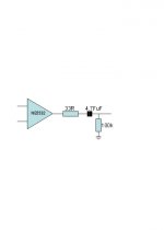
eradoncic said:That's very similar to this "receip" for making good sounding even the notorious NE5532, which is said it is taken from proffesional electronics.
OK, I did not check it yet (but I'm planing), but it seems that the same 100k resistor to ground make sense (at least soundwise)
That's quite different. In that case there is a coupling capacitor. Then the resistor has the purpose to discharge the capacitor when you disconnect the amp. That is more a question of avoiding pops and sparks when plugging in equipment, as far as I understand.
Christer said:Then the resistor has the purpose to discharge the capacitor when you disconnect the amp.
Not just that. In that case, the resistor, in parallel with the input resistor to ground on the next stage, forms the high pass filter.
carlosfm said:
Not just that. In that case, the resistor, in parallel with the input resistor to ground on the next stage, forms the high pass filter.
Yes, but that is hardly the reason for the resistor to ground. By using such a resistor we increase the corner frequency, which is usually not desired, but if that is what we want, then it would be better to choose a smaller capacitor instead. The resistor could be there to give a well-defined corner frequency if the input impedance of the following unit is unknown but known to be much higher than the resistor though. However, with a value of 100k, that is not likely to be the reason either.
- Status
- Not open for further replies.
- Home
- Amplifiers
- Chip Amps
- Good replacment for BB OPA 2604/604