Hi Mooly
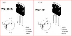
I am again, I am happy to say that My retailer have mosfets and it have prised 11.5 US doller/complementary pair but the part number is N chennel 2SK1058 and 2SJ162
ataul
Perfect 🙂 Just make sure you get the pinouts correct.
Only two important things to watch... all in the original thread.
First the opamp must be aTL071 type as this works in this application with a single negative 12 volt rail... other types are not guaranteed too without the added complication of a positive rail.
Second, a relay delay on the speaker output is pretty much essential. It needn't be complex, just a transistor and RC delay on the base is sufficient.
It's needed because the output takes a few seconds to fully settle to 0.00 volts due to the integrator on the opamp.
When you are ready to test it, it all works without any output devices connected at all (obviously with no load connected) so you can test and confirm all is OK
Attachments
Mooly
Thanks for advice. Ok i have good and simple speaker delay with dc detector circuit that was proven circuit. I have used it in my many previus amp circuits and it save my speakers too. I have TL071 in my junk box 🙂
Best regard
Ataul
Thanks for advice. Ok i have good and simple speaker delay with dc detector circuit that was proven circuit. I have used it in my many previus amp circuits and it save my speakers too. I have TL071 in my junk box 🙂
Best regard
Ataul
hi mooly
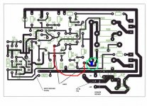
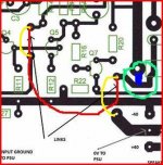
On the PCB design u mention that in two point link, i have mark here in Red line.Why u are not link this point (in the circle with blue line)
Have u more modified PCB design?
Can i use low noise BC550and BC560 in the small signal side?
Ataul
On the PCB design u mention that in two point link, i have mark here in Red line.Why u are not link this point (in the circle with blue line)
Have u more modified PCB design?
Can i use low noise BC550and BC560 in the small signal side?
Ataul
Attachments
Last edited:
Remember the pinouts for the BC's are different to the 2N5551/2N5401. Base is still in the middle, collector and emmiter reversed.
Hi Mooly
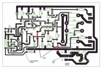
Can you give me only track layout.you post track with component layout
I canot separate them to macking PCB
Ataul
Can you give me only track layout.you post track with component layout
I canot separate them to macking PCB
Ataul
No I haven't... but,
have you ever used Diptrace ? freeware. It's fairly easy to use.
Downloads :: DipTrace
if you are interested, I can do a similar PCB (or you can 🙂) and then you can print directly (way better image quality). I print onto Jetstar transparencies directly on an inkjet printer and then use UV lightbox etc. The quality is unbelievable... absolutely perfect. This was the last one I did, posts 22 and 23.
http://www.diyaudio.com/forums/headphones/160646-germanium-single-ended-class-headphone-amp-2.html
- Status
- Not open for further replies.
- Home
- Amplifiers
- Solid State
- good power amp schematic