Hi
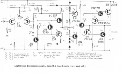
I have exhumed this unusual amplifier based on a patented idea: "constant power amplifier" by Nguyen Tan Tai:
Electronic power amplifier for delivering a constant power into a load impedance - United States Patent 4095189
Claims are no global feedback, load invariant output power, unexpected reproduction quality, and tube-like sound.
It is claimed that fifteen(!) 8Ω series-connected speakers do not alter the acoustic power.
I leave you to judge.....
Have fun!
Attachments
Hi
I have exhumed this unusual amplifier based on a patented idea: "constant power amplifier" by Nguyen Tan Tai:
Electronic power amplifier for delivering a constant power into a load impedance - United States Patent 4095189
Claims are no global feedback, load invariant output power, unexpected reproduction quality, and tube-like sound.
It is claimed that fifteen(!) 8Ω series-connected speakers do not alter the acoustic power.
I leave you to judge.....
Have fun!
great!
do you think it will work with modern output transistors without tweaking?
regards
Class B (do we allow it a few milliamps for good measure)... 2N3055/2955... no gfb... sounds tube like.
Have you run a sim Elvee ?
Have you run a sim Elvee ?
Yeah, I have run a sim, but I haven't disclosed the results yet, as I wanted to hear unbiased opinions first 😀sounds tube like.
Have you run a sim Elvee ?
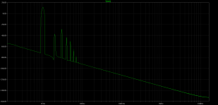
The THD figure shows that it definitely sounds tube-like, and even overdoes it by quite a bit
The THD figure shows that it definitely sounds tube-like, and even overdoes it by quite a bit
so bad?😀
I like this circuit😉
could you pickup asc file?
thank you in advance
That's impossible.It is claimed that fifteen(!) 8Ω series-connected speakers do not alter the acoustic power.
EDIT: To be more precise: what's shown is a reasonable conventional poweramp.
Let's not forget that an amplifier can be seen as an audio modulated "valve" between the PSU and the speaker.
The amplifier will not create power which was not available at the PSU first.
Won't supply voltage higher than the rail(s) so when you rise load impedance you soon hit the rails, and can't supply current higher than what's available, so that quickly limits power into lower impedances, besides increasing losses in a horrible way.
That's why amplifiers have a rated "optimum" impedance; as an example 8 ohms, and can deliver reasonable power into 2X and 1/2X that (16 or 4 ohms) but to claim you can raise impedance 15X and keep power *constant* is ludicrous.
To be even more precise: that can be done, of course, with a multitapped output transformer .... but none such is to be seen at that schematic 🙄
Last edited:
You asked for it, here it is, but be warned: it is a real stinker!so bad?😀
I like this circuit😉
could you pickup asc file?
thank you in advance
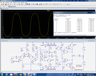
First, maximum output before clipping (sort of), and THD
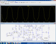
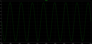
Second the clipping (sort of) behavior (yes, it happens as soon as ~14Vpp, and I have corrected some resistor values otherwise it is still worse)
Third the temperature stability (or instability rather) of the Iq and output offset.
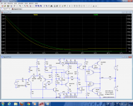
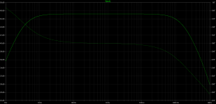
I forgot to mention: the -3dB small signal frequency response is .... 14KHz! Really tube-like!
Attachments
I have exhumed this unusual amplifier based on a patented idea: "constant power amplifier" by Nguyen Tan Tai:
Electronic power amplifier for delivering a constant power into a load impedance - United States Patent 4095189""
OK - you can bury it again! 🙂
Electronic power amplifier for delivering a constant power into a load impedance - United States Patent 4095189""
OK - you can bury it again! 🙂
You asked for it, here it is, but be warned: it is a real stinker!
First, maximum output before clipping (sort of), and THD
Second the clipping (sort of) behavior (yes, it happens as soon as ~14Vpp, and I have corrected some resistor values otherwise it is still worse)
Third the temperature stability (or instability rather) of the Iq and output offset.
I forgot to mention: the -3dB small signal frequency response is .... 14KHz! Really tube-like!
Thank you Elvee!
IMO, there are an infinite number of way to connect electronic components to form a circuit. Most of them are wrong.
Still, it's always interesting to see what people have tried.
Still, it's always interesting to see what people have tried.
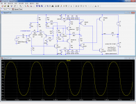
with BD139/140 and MJL3281/1302 and after setting offset at zero it swings well ~15Vpp with light compression.
I think it would be very good guitar amp.
I think it would be very good guitar amp.
I forgot to mention: the -3dB small signal frequency response is .... 14KHz! Really tube-like!
You don't like tubes much, do you? 😉
FWIW tubes usually have tens or hundreds of MHz frequency response.
The humble and very common 12AT7 is :
6L6 was the RF power tube in WW2 Sherman tank radio transmitters and afterwards in many Amateur transceivers.Originally the tube was intended for operation in VHF circuits, such as TV sets and FM tuners, as an oscillator/frequency converter, but it also found wide use in audio as a driver and phase-inverter in vacuum tube push-pull amplifier circuits.

Excellent work! This doesn't change it into a winner, but at least it has been rescued from abysmal depths.with BD139/140 and MJL3281/1302 and after setting offset at zero it swings well ~15Vpp with light compression.
I think it would be very good guitar amp.
Now, what about the load invariance claim? For me, it is simply a current output amplifier. I think the damping factor must be rather disastrous.
As long as tube amplifiers will require coupling capacitors and output transformers, this will go mostly unnoticed (except for the rare OTL designs)FWIW tubes usually have tens or hundreds of MHz frequency response.
Excellent work! This doesn't change it into a winner, but at least it has been rescued from abysmal depths.
Now, what about the load invariance claim? For me, it is simply a current output amplifier. I think the damping factor must be rather disastrous.
Elvee, so let me know what is in your opinion the greatest advantage of this vetust amp?
BTW do you think that an amplifier must have an high dumping factor to sound good?
Francesco.
I am always on the look for original, clever, or unexpected schemes.Elvee, so let me know what is in your opinion the greatest advantage of this vetust amp?
This one caught my eyes because of the "constant power" claim, and the bizarre attending circuitry (the one I removed in the improved version).
I said to myself: the claim is impossible to fulfill, at least with a linear circuit: a constant voltage output is linear, but the output power is inversely proportional to the load resistance, and a constant current is linear too, but has an output proportional to the resistance.
Constant power requires something in-between: a current proportional to the square root of the load. If it is done in real time (ie not with an AGC), it can only lead to a non-linear transfer function.
The "constant power engine" simply dumps the largest part of the drive current, removing in effect one layer of amplification.
That such a thing could be patented puzzled me: why go to such lengths, create a delusional mathematical demonstration for such a worthless scheme?
I sort of hoped there was more to it, but sadly, as is always the case, it is simply a big heap of bovine waste-product
Not necessarily, but a current output over-emphasizes resonances and is generally detrimental. But not always.BTW do you think that an amplifier must have an high dumping factor to sound good?
Some amplifiers (tube for instance) have a high impedance output, most decent solid state and tube amplifiers have a very low output impedance, and some amplifiers, tube or solid-state have a negative resistance created deliberately.
interesting vintage approach.
here the pdf-paper:
http://www.pat2pdf.org/patents/pat4095189.pdf
Do you know, in which commercial amplifier brand/model this topology is in use?
Maybe a small manufactur in France like YBA, Cairn-EZO or Lavardin
From the same Inventor there is this patent:
Patent EP0159257B1 - Electronic circuit for measuring very weak signals superposed on a high ... - Google Patents
I am always on the look for original, clever, or unexpected schemes.
This one caught my eyes because of the "constant power" claim, and the bizarre attending circuitry (the one I removed in the improved version).
I said to myself: the claim is impossible to fulfill, at least with a linear circuit: a constant voltage output is linear, but the output power is inversely proportional to the load resistance, and a constant current is linear too, but has an output proportional to the resistance.
Constant power requires something in-between: a current proportional to the square root of the load. If it is done in real time (ie not with an AGC), it can only lead to a non-linear transfer function.
The "constant power engine" simply dumps the largest part of the drive current, removing in effect one layer of amplification.
That such a thing could be patented puzzled me: why go to such lengths, create a delusional mathematical demonstration for such a worthless scheme?
I sort of hoped there was more to it, but sadly, as is always the case, it is simply a big heap of bovine waste-product
Not necessarily, but a current output over-emphasizes resonances and is generally detrimental. But not always.
Some amplifiers (tube for instance) have a high impedance output, most decent solid state and tube amplifiers have a very low output impedance, and some amplifiers, tube or solid-state have a negative resistance created deliberately.
So I understand that you have posted the schematic not because you shared this idea but only for curiosity and pheraps to humiliate the author.
I'm sorry you feel that way.
I, however, I paused to read this topic just because I was attracted by the phrase "constant power amp" because of something like that I'm working on for a few years and this is a very serious thing for me. For a long time I thought I'd be alone to think so, then a few months ago a German guy sent me an article by Stanley White about his "POWRTRON AMPLIFIER" which shares a similar idea.
Since the relationship between the power from one side and the voltage, the current and the impedance of the other side are non-linear but quadratic relationship, then the big problem is to find a simple and fast circuit (no IC) which does not introduce distortions (no diodes) that implements such a function.
Now coming back to the idea of Tai Nguyen-Tan, I think it was good. Less good seems to me the real implementation of the same, because he dredge the bias current, making it variable, which for other needs, it should be quite stable. Another issue from the attached diagram is that the control loop goes too far away from the output, with associated problems to the inevitable delays in the process of adjustment.
My idea by such amplifier is developed in a different way.
Simple example i will post later.
Francesco.
- Status
- Not open for further replies.
- Home
- Amplifiers
- Solid State
- Good old technology?