I don't care who uses my designs as long as it's not for profit beyond one's means. And I'd appreciate it if you'd tell me about your project if you use something of mine.
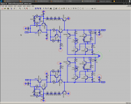
Krisfr, that is a 39R resistor, let me make a new schematic without the stupid grid...
EDIT: Attached
- keantoken
Krisfr, that is a 39R resistor, let me make a new schematic without the stupid grid...
EDIT: Attached
- keantoken
Attachments

Last edited:
could the 7815 be driven over voltage at start up due to discharged caps appearing as short circuits?
I guess you can say that too. 220uF is a bit on the big side and if the in/out voltage differential at start up is out of specification, yes the 7805 will pop.
A series resistor at the input side of the 7805 might do the trick as it will drop voltage at across it at start up.
OS are you talking about figure "D" on mouser catalog page 1582
"D" is the standard 5mm pitch euroterminal , they make a 7.5mm lead pitch one that will handle 15A as well. Fastons are much cheaper but you have to solder a spade onto the wire.
I even mix and match euro's and fastons. Fastons for grounding and euros for the rails (lower voltage/amperage projects - below)... many options for physical layouts and interconnects.
OS
Attachments
Input voltage to the 7815 is about 25V. So that makes 25W shorted into capacitor with 1A current limit. Surprise, this is above the 20W max in the datasheet... However this assumes an instant startup voltage. It will normally have the rise of a 60Hz sinewave, which should be more than long enough for the output side to catch up, no?
- keantoken
- keantoken
Okay, for the LM7815 not to blow it needs the input to rise at least 5V before the input gets to 25. 1A (current limit) will fill a 220uF to 1V in 220uS. 5*220u=1.1mS. It takes 1/4 of a 60Hz wave to bring the 25V rail to max, so .25/60=4.17mS. So no, the 7815 can't blow from over voltage because the output voltage rises too fast.
- keantoken
- keantoken
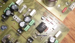
All grounds should come together except C9 and C16 which should be next to the rectifiers. Green should be the star.
- keantoken
- keantoken
You might want to put a little bit more distance between the primary traces, to meet creepage distance safety.
Also, putting the primary faston connectors physically closer to each other allows easier (and neater) wire lead twisting.
Also, putting the primary faston connectors physically closer to each other allows easier (and neater) wire lead twisting.
Hey guys, has anyone noticed how the MC7815 has better specs than the rest? Fairchild, STMicro, etc. all have 10 times the output impedance. Interesting thing about the KIA7815 is that they also specify output noise, 110uV (wow that's a lot).
- keantoken
- keantoken
110uV (wow that's a lot).
My god!, that's 0.00000733% of the total voltage output...shocking!
😎
Boy that is a lot! I wonder what a good value would be? As an added note, the high frequency output impedance will be no more than the impedance of the bypass cap. This should be in the millohm and sub-microhenry range.
Yes, if I floated the 7815 at 15KV it would be .00000000733%. So if I floated it at 15MV, I would technically have an ultra-low noise supply, right? Right? It's not very useful to compare AC noise to DC voltage.
My scope measures to 10uV and compared to circuits I've made, 110uV is actually a lot. Mostly what I've measured is at or below 10uV. Of course this is discrete DIY circuits, not IC's.
- keantoken
My scope measures to 10uV and compared to circuits I've made, 110uV is actually a lot. Mostly what I've measured is at or below 10uV. Of course this is discrete DIY circuits, not IC's.
- keantoken
Last edited:
Sawreyrw, a 100V 100uF cap will have ESR in the hundreds of mR, so this eliminates that line of thought as far as the upper rails supply is concerned. And as far as Denon repair is concerned, I don't plan on any "upgrades", just get it fixed.
- keantoken
- keantoken
Right?
Whatever floats your boat kean. Build a reasonable 7815 regulator circuit and connect your headphones through a cap. Report on the AC noise you can actually hear.
You see it on your scope - that's fine, it exists. What you are after is the DC component to run your (most likely a lot more noisy) circuit.
The Zener is to ensure startup. Salas' circuit doesn't have this and seems to work anyways, but it is different. Q1 and Q9 need sink'd.
The difference between this circuit and my last will be in the PPB or low PPM. The need for the "enhancements" is to increase the DC PSRR. Otherwise I wouldn't have bothered.
Those who want can still build the earlier circuit, it is still valid, but could quite possibly be overkill.
- keantoken
The difference between this circuit and my last will be in the PPB or low PPM. The need for the "enhancements" is to increase the DC PSRR. Otherwise I wouldn't have bothered.
Those who want can still build the earlier circuit, it is still valid, but could quite possibly be overkill.
- keantoken
- Home
- Amplifiers
- Solid State
- Goldmund Mods, Improvements, Stability